Prolon C1000 Series Hardware Manual
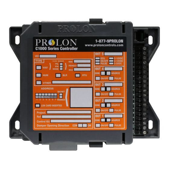
Rooftop controller
Hide thumbs
Also See for C1000 Series:
- Hardware manual (23 pages) ,
- Quick start manual (10 pages) ,
- Operational manual (19 pages)
Table of Contents
Advertisement
Quick Links
Download this manual
See also:
Hardware Manual
Advertisement
Table of Contents

Related Manuals for Prolon C1000 Series


Summary of Contents for Prolon C1000 Series
- Page 1 Hardware Guide Rooftop Controller C1000 Series Specifications and Operational Guide www.proloncontrols.com info@proloncontrols.com REV 6.3 PL-HRDW-C1000RTU-C/F-EN-V63...
-
Page 2: Table Of Contents
PL-C1000 SERIES BASIC ROOFTOP HARDWARE GUIDE www.proloncontrols.com Table of Contents GENERAL INFORMATION ......................3 PL-C1000 Basic Rooftop Controller ......................3 Description ................................... 3 General Behaviour ............................... 3 Operation Sequence ............................. 4 General ..................................4 Occupied Mode ................................4 Unoccupied Mode ................................ 5 COMPONENTS .......................... -
Page 3: General Information
All these parameters can be accessed by using the ProLon Focus software. Montréal info@proloncontrols.com... -
Page 4: Operation Sequence
Operation Sequence General The ProLon C1000 Basic Rooftop controller receives readings from three temperature sensors located outside, in the return duct and in the supply duct. Also, as a Master device, it receives data from the zone controllers sent on the network bus. A dry contact originating from an external timer signals the occupancy status (optional) to the Master. -
Page 5: Unoccupied Mode
PL-C1000 SERIES BASIC ROOFTOP HARDWARE GUIDE www.proloncontrols.com Unoccupied Mode The fan can be configured to operate in intermittent mode. When there is a cooling or heating demand from any single zone, the Rooftop controller will activate the fan and the cooling outputs as long as all temperature limits, delays and other related parameter are respected. -
Page 6: Components
PL-C1000 SERIES BASIC ROOFTOP HARDWARE GUIDE www.proloncontrols.com COMPONENTS Component Identification BIAS TERM BIAS TERM Legend: A = Addressing Dipswitch B = Output 1 Dipswitch C = Output 2 Dipswitch D = Output 3 Dipswitch E = Output 4 Dipswitch F = Master reset button... -
Page 7: Leds
PL-C1000 SERIES BASIC ROOFTOP HARDWARE GUIDE www.proloncontrols.com LEDs Green light: reception from interface Red light: Green pulsing: transmission to Red light: indicates that the main bus transmission to CPU is online interface Reserved Green light: Reception from main bus Status light for... -
Page 8: Input And Output Identification
PL-C1000 SERIES BASIC ROOFTOP HARDWARE GUIDE www.proloncontrols.com Input and Output Identification All the inputs and outputs of the C1000 use pluggable screw type terminal blocks with elevator style clamping, which make connections easier and more secure. For incoming communication from a remote computer or network controller, an RJ45 type connector is available. -
Page 9: Addressing Dipswitch Configuration For Network Communication
Therefore, the corresponding values are 1, 2 and 8, giving an address sum of 11. The ProLon network allows a maximum of 127 addresses, therefore 127 controllers. Jumper to supply power to the RJ45 plug The RJ45 jumper lets the user select if voltage that will appear on pin #7 of the RJ45 plug. This can be used to power a device attached to the RJ45 plug, such as a digital sensor or interface. -
Page 10: Inputs
PL-C1000 SERIES BASIC ROOFTOP HARDWARE GUIDE www.proloncontrols.com INPUTS Temperature Sensors The C1000 Rooftop controller has three analog inputs that monitor outside air, return air and supply air temperatures (see Figure 2) and will integrate these readings into its control sequence. The sensors used are standard 10k type 3 thermistors that share a single common connection. -
Page 11: Occupancy Mode (Night Setback)
PL-C1000 SERIES BASIC ROOFTOP HARDWARE GUIDE www.proloncontrols.com Occupancy Mode (Night Setback) Dry Contact originating from an External Timer: Temperature setback savings can be obtained by using a dry contact originating from an external timer to switch the controller from occupied to unoccupied mode. The timer contact used must be connected to the "OCC"... -
Page 12: Outputs
(PI) to ensure precise adjustment of the device. All configurations are performed via the ProLon Focus software. An integrated resettable fuse protects each of the outputs of the C1000 against current surges and short circuits. -
Page 13: Typical Connection Of The Triac Outputs 1 Through 4
PL-C1000 SERIES BASIC ROOFTOP HARDWARE GUIDE www.proloncontrols.com Typical Connection of the Triac Outputs 1 through 4 On the C1000 Rooftop controller, all triac outputs must be set to SOURCE mode because they all share a single source supply: the equipment’s transformer. All triac outputs have a SOURCE / SINK configuration switch;... -
Page 14: Dmux-4J Connection On Output 2 For Stage 3 Or 4 Cooling
PL-C1000 SERIES BASIC ROOFTOP HARDWARE GUIDE www.proloncontrols.com DMUX-4J Connection on Output 2 for Stage 3 or 4 Cooling When 3 or 4 stages of cooling are required, the C1000 Rooftop controller must be equipped with a DMUX-4J. The DMUX-4J input is only connected to Output 2 on the C1000 Rooftop controller. The DMUX-4J must be configured to “Sequenced Relay Control”... -
Page 15: Pta2 Connection On Output 2 For Analog Cooling
PL-C1000 SERIES BASIC ROOFTOP HARDWARE GUIDE www.proloncontrols.com PTA2 Connection on Output 2 for Analog Cooling When analog cooling is required, the C1000 Rooftop controller must be equipped with a PTA2 v.1. The PTA2 input is connected to Output 2 on the C1000 Rooftop controller. The input pulse range must be set to 0.1-10 sec. -
Page 16: Power Source & Network
Figure 8: Connecting the 24VAC power source Network Communication The ProLon C1000 Rooftop controller is primarily designed to work with ProLon zone controllers. When they are networked the Rooftop and zone controllers all communicate in real-time. The network connections are made using the network terminal blocks located on the C1000 controller (see Figure 9). -
Page 17: Technical Specifications
Dimensions: 157 mm x 133 mm (6.2" x 5.2" ) Environment: 0-50 ºC (32-122 ºF) Non-Condensing The performance specifications are nominal and conform to acceptable industry standards. ProLon Inc. will not be liable for damages resulting from misapplication or misuse of its products. -
Page 18: Compliance
Caution: Any changes or modifications not approved by ProLon can void the user’s authority to operate the equipment. Note: This equipment has been tested and found to comply with the limits for a Class B digital device, pursuant to part 15 of the FCC Rules. -
Page 19: Overall Dimensions
No part of this document may be photocopied or reproduced by any means, or translated to another language without prior written consent of ProLon. All specifications are nominal and may change as design improvements are introduced. ProLon shall not be liable for damages resulting from misapplication or misuse of its products.
Need help?
Do you have a question about the C1000 Series and is the answer not in the manual?
Questions and answers