Prolon C1050 Series Hardware Manual
Flexio controller
Hide thumbs
Also See for C1050 Series:
- Specifications and operational manual (18 pages) ,
- Hardware manual (17 pages) ,
- Technical reference manual (98 pages)

Related Manuals for Prolon C1050 Series


Summary of Contents for Prolon C1050 Series
- Page 1 HARDWARE GUIDE FlexIO Controller C1050 Series Specifications and Operational Guide www.proloncontrols.com | info@proloncontrols.com 17 510, rue Charles, Suite 100, Mirabel, QC, J7J 1X9 REV. 7.3.0 PL-HRDW-FLX-C1050-EN...
-
Page 2: Table Of Contents
Table of Contents General Information ............................... 4 PL-C1050 FLX Controller ....................................4 Description ..........................................4 Features ..........................................4 Components .........................................5 Components Identification .....................................5 LEDs ............................................6 Address Configuration for Networking ..............................6 Input and Output Identification ..................................7 Inputs ....................................8 Analog Input.........................................8 Signal: Thermistor.......................................8 Signal: Contact ........................................9 Signal: Voltage ........................................9 Signal: Current ........................................ - Page 3 Table of Figures Figure 1 - Component Identification ..................................5 Figure 2 - LEDs Identification ....................................6 Figure 3 - Addressing Dipswitches ..................................6 Figure 4 - Input and Output Identification ................................7 Figure 5 - Analog input ......................................8 Figure 6 - Connecting a temperature sensor to analog input 1 .......................8 Figure 7 - Connecting a dry contact to analog input 1 ..........................9 Figure 8 - Connecting voltage based sensors..............................9 Figure 9 - Connecting current based sensors ..............................
-
Page 4: General Information
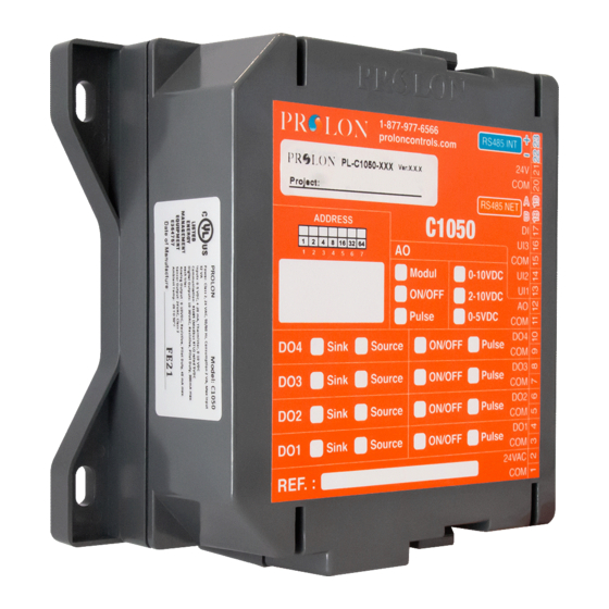
The C1050 FlexIO is a general purpose HVAC controller whose inputs and outputs can be individually configured for use in various applications. Unlike most Prolon controllers, the FlexIO is not aimed at a specific HVAC sequence or piece of equipment, and instead can be used to perform any outlying functions that are not usually covered by existing Prolon devices. -
Page 5: Components
Components Components Identification 24VAC BIAS THERM BIAS THERM Figure 1 - Component Identification Legend: A - Analog Input Signal Mode Jumpers B - Addressing dipswitch C - Jumpers for terminating and bias resistors for the INT port (see I) D - Jumpers for terminating and bias resistors for the NET port (see K) E - SOURCE/SINK dipswitch for Output 4 F - SOURCE/SINK dipswitch for Output 3 G - SOURCE/SINK dipswitch for Output 2... -
Page 6: Leds
The example below shows the switches 1, 2 and 4 on the ON position. So the corresponding values are 1, 2 and 8, giving an address sum of 11. (1+2+8=11) The Prolon network allows a maximum of 127 addresses, therefore 127 controllers. Figure 3 - Addressing Dipswitches... -
Page 7: Input And Output Identification
The C1050 FlexIO Controller has two separate communication ports offering the same functionality on each. Both act as ports for incoming Modbus communications from other Prolon devices or interfaces, such as a Network Controller or remote computer with Prolon Focus software. -
Page 8: Inputs
Inputs Analog Input The C1050 series controllers are equipped with three general purpose analog inputs. These inputs can be configured to receive signals of the following types: • Thermistor (Ω) • 0-5V • 4 -20mA • 0-10V When a thermistor is used, the thermistor must be 10KΩ TYPE 3. -
Page 9: Signal: Contact
Signal: Contact The C1050 FlexIO controller inputs can be used to monitor digital contacts. Please refer to Figure 7 to see how to correctly connect them. Contact Figure 7 - Connecting a dry contact to analog input 1 Signal: Voltage The C1050 FlexIO controller inputs can be used to monitor the voltage signal produced by a variety of transducers (such as pressure, gas, humidity and more). -
Page 10: Signal: Current
Signal: Current The C1050 FlexIO controller inputs can be used to monitor the current signal produced by a variety of transducers (such as pressure, gas, humidity and more). The C1050 requires a 250 Ohm resistor in parallel with the COMMON. Please refer to Figure 10 for correct wiring. -
Page 11: Outputs
The C1050 FlexIO controller contains 5 customizable outputs; four triac ON/OFF outputs (24VAC) and one analog output (0-10VDC). Output configuration is performed via the Prolon Focus software. An integrated resettable fuse protects each of the outputs of the C1050 against current surges and short circuits. This protection will cut the current to the output as soon as an overload condition is detected. -
Page 12: Typical Connection Of Digital Outputs
2) Switch position to obtain a SINK passive output: Switch for Output 4 Isolated dry contact (On/O ) Figure 11 - Output in SINK mode Typical Connection of Digital Outputs Two types of configurations are possible: 1) Active output (SOURCE). The C1050 is actively powering the load. External Load Figure 12 - Connection of active outputs 3 and 4 2) Passive output (SINK). -
Page 13: Typical Connection Of Analog Outputs
Typical Connection of Analog Outputs Two types of configuration are possible: 1) The C1050 powers the load and provides a control signal. 24 VAC power (From terminal block #2 of the controller) Controlled 0-10v Load Figure 14 - Connecting the analog output (controller powered) 2) The C1050 only provides the control signal to the load, which is powered by an external source. -
Page 14: Power Source / Network
Power Source The Prolon C1050 controller is powered by a 24 VAC power source connected using the "COM" terminal and the "24 VAC" terminal. The common for all inputs and outputs are the same as the power source’s common (exception: when an out- put is set to passive, the common for this output will not correspond to the power source common). -
Page 15: Technical Specifications
Certification: UL916 Energy Management Equipment, CAN/CSA-C22.2, RoHS, FCC part 15: 2012 class B The performance specifications are nominal and conform to acceptable industry standards. Prolon Inc. will not be liable for damages resulting from misapplication or misuse of its products. -
Page 16: Compliance
Caution: Any changes or modifications not approved by Prolon can void the user’s authority to operate the equipment. Note: This equipment has been tested and found to comply with the limits for a Class B digital device, pursuant to part 15 of the FCC Rules. -
Page 17: Overall Dimensions
No part of this document may be photocopied or reproduced by any means, or translated to another language without prior written consent of Prolon. All specifications are nominal and may change as design improvements are introduced. Prolon shall not be liable for damages resulting from misapplication or misuse of its products.
Need help?
Do you have a question about the C1050 Series and is the answer not in the manual?
Questions and answers