Prolon PL-C1000 Operational Manual
Boiler controller
Hide thumbs
Also See for PL-C1000:
- Installation manual (7 pages) ,
- Hardware manual (19 pages) ,
- Hardware manual (17 pages)

Subscribe to Our Youtube Channel
Related Manuals for Prolon PL-C1000


Summary of Contents for Prolon PL-C1000
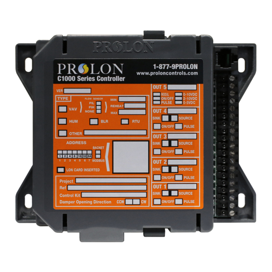
- Page 1 Hardware Guide Boiler Controller C1000 Series Specifications and Operational Guide www.proloncontrols.com info@proloncontrols.com REV 6.3 PL-HRDW-C1000BLR-C/F-EN-V63...
-
Page 2: Table Of Contents
C1000 SERIES BOILER CONTROLLER HARDWARE GUIDE www.proloncontrols.net Table of Contents GENERAL INFORMATION ..........................3 PL-C1000 Boiler Controller ........................... 3 Description ................................... 3 General Behaviour ............................... 3 Operating Sequence ............................. 4 General ..................................4 Parallel Pump Sequence ............................. 4 Follower Pump Sequence ............................5 COMPONENTS ............................. -
Page 3: General Information
The various programming options also allow the user to modify the lead-lag sequences, conditions for pump activity and the influence of schedules or other data received over the network. All these parameters can be accessed and modified by using the ProLon Focus software. -
Page 4: Operating Sequence
In addition to the temperature sensors, it also has an input for proof of operation of the pumps. It can receive data from ProLon master controllers such as outside temperature, occupancy, or the average heating request of the building. The controller then analyzes all the data and activates the appropriate outputs to respond accordingly, within parameters set by the temperature sensors and other safety limits. -
Page 5: Follower Pump Sequence
C1000 SERIES BOILER CONTROLLER HARDWARE GUIDE www.proloncontrols.net Follower Pump Sequence This sequence is intended for hydronic systems where there is a primary and secondary loop. The primary pump is activated based on outside temperature or upon a call for heating, or both. The secondary pump will be activated simply when there is proof of operation of the primary pump. -
Page 6: Components
C1000 SERIES BOILER CONTROLLER HARDWARE GUIDE www.proloncontrols.net COMPONENTS Component Identification BIAS TERM BIAS TERM Legend: A = Addressing dipswitch B = Jumpers for terminating and bias resistors for the NET port (see J) C = Jumpers for terminating and bias resistors for the INT port (see K) D = SOURCE/SINK dipswitch for Output 4 (Boiler Stage 2) E = SOURCE/SINK dipswitch for Output 3 (Boiler Stage 1) F = SOURCE/SINK dipswitch for Output 2 (Pump 2) -
Page 7: Leds
C1000 SERIES BOILER CONTROLLER HARDWARE GUIDE www.proloncontrols.net LEDs The C1000 has various LEDs which are linked to different functions and outputs of the controller. Each LED is individually identified to help the user make a quick visual diagnostic of the controller’s activity and status. Green light: Reception Red light: Sending from INT port... -
Page 8: Address Configuration For Networking
The example on Figure 1 shows the switches 1, 2 and 4 on the ON position. So the corresponding values are 1, 2 and 8, giving an address sum of 11. (1+2+8=11) The ProLon network allows a maximum of 127 addresses, therefore 127 controllers. Jumper to supply power to the RJ45 plug The RJ45 jumper lets the user select the voltage that will appear on pin #7 of the RJ45 plug. -
Page 9: Input And Output Identification
The C1000 Boiler Controller has two separate communication ports offering the same functionality on each. Both act as ports for incoming Modbus communications from other ProLon devices or interfaces, such as a Network Controller or remote computer with ProLon Focus software. -
Page 10: Inputs
C1000 SERIES BOILER CONTROLLER HARDWARE GUIDE www.proloncontrols.net INPUTS Temperature Sensors The C1000 Boiler controller has three analog inputs that monitor outside air, supply water and return water temperatures (see Figure 2) and will integrate these readings into its control sequence. The sensors used are standard 10k type thermistors that share a single common connection. -
Page 11: Proof Of Pump
C1000 SERIES BOILER CONTROLLER HARDWARE GUIDE www.proloncontrols.net Proof of Pump The C1000 has one digital inputs dedicated to the proof of pump signals. Please refer to Figure 3 see how to correctly connect it. To indicate proof of pump, the contact must be closed. If no proof of pump signal is available, you must short the corresponding input, or else the controller will interpret the absence of signal as a pump malfunction and no heating action will be taken. -
Page 12: Outputs
The C1000 Boiler controller contains 5 customizable outputs; four triac ON/OFF outputs (24VAC) and one analog output (0-10VDC). Output configuration is performed via the ProLon Focus software. An integrated resettable fuse protects each of the outputs of the C1000 against current surges and short circuits. -
Page 13: Configuration Of Digital Outputs
C1000 SERIES BOILER CONTROLLER HARDWARE GUIDE www.proloncontrols.net Configuration of Digital Outputs The digital triac outputs are configurable (SOURCE/SINK) via a switch located on the board. Simply move the switch to obtain either a SOURCE active output (1) or a SINK passive output (2). 1) Switch position to obtain a SOURCE active output (see Figure 4): 24 VAC Output (On/Off) Switch for... -
Page 14: Typical Connection Of Digital Outputs
C1000 SERIES BOILER CONTROLLER HARDWARE GUIDE www.proloncontrols.net Typical Connection of Digital Outputs Two types of configurations are possible: 1) Active output (SOURCE). The C1000 is actively powering the load. (see Figure 6) External Load 24 v Figure 6: Connection of active outputs 3 and 4 2) Passive output (SINK). -
Page 15: Typical Connection Of The Analog Output
C1000 SERIES BOILER CONTROLLER HARDWARE GUIDE www.proloncontrols.net Typical connection of the analog output Two types of configuration are possible: 1) The C1000 powers the load and provides a control signal (see Figure 8) 24 VAC power (From terminal block 24 v Controlled #2 of the controller) 0-10v Load 0-10v Figure 8: Connecting the analog output (controller powered) 2) The C1000 only provides the control signal to the load, which is powered by an external source (see... -
Page 16: Power Source / Network
The C1000 controller’s default communication protocol is Modbus RTU over RS485. The addressing is done with the addressing dipswitch located on the C1000 card (see Figure 1). The network connections are made using the NET terminal block located on the ProLon C1000 controller (see Figure 11). -
Page 17: Technical Specifications
Dimensions: 157 mm x 133 mm (6.2" x 5.2" ) Environment: 0-50 ºC (32-122 ºF) Non-Condensing The performance specifications are nominal and conform to acceptable industry standards. ProLon Inc. will not be liable for damages resulting from misapplication or misuse of its products. -
Page 18: Compliance
Caution: Any changes or modifications not approved by ProLon can void the user’s authority to operate the equipment. Note: This equipment has been tested and found to comply with the limits for a Class B digital device, pursuant to part 15 of the FCC Rules. -
Page 19: Overall Dimensions
© Copyright 2016 ProLon. All rights reserved. No part of this document may be photocopied or reproduced by any means, or translated to another language without prior written consent of ProLon. All specifications are nominal and may change as design improvements are introduced. ProLon shall not be liable for damages resulting from misapplication or misuse of its products.
Need help?
Do you have a question about the PL-C1000 and is the answer not in the manual?
Questions and answers