Prolon C1050 Series Hardware Manual
Humidifier controller
Hide thumbs
Also See for C1050 Series:
- Specifications and operational manual (18 pages) ,
- Hardware manual (17 pages) ,
- Technical reference manual (98 pages)

Subscribe to Our Youtube Channel
Related Manuals for Prolon C1050 Series


Summary of Contents for Prolon C1050 Series
- Page 1 HARDWARE GUIDE Humidifier Controller C1050 Series Specifications and Operational Guide www.proloncontrols.com | info@proloncontrols.com 17 510, rue Charles, Suite 100, Mirabel, QC, J7J 1X9 REV. 7.3.0 PL-HRDW-HU-C1050-C/F-EN...
-
Page 2: Table Of Contents
Table of Contents General Information ............................... 4 PL-C1050 Humidity Controller ..................................4 Description ..........................................4 General Behaviour ......................................4 Operating Sequence ............................... 5 Humidification ........................................5 Dehumidification ........................................5 Components ..................................6 Component Identification ....................................6 LEDs ............................................7 Address Configuration for Networking ..............................7 Input and Output Identification ..................................8 Inputs .................................... - Page 3 Table of Figures Figure 1 - Component Identification ..................................6 Figure 2 - LEDs Identification ....................................7 Figure 3 - Addressing Dipswitches ..................................7 Figure 4 - Input and Output Identification ...............................8 Figure 5 - Analog input ......................................9 Figure 6 - Connecting the Outside Air Sensor ..............................9 Figure 7 - Connecting the Humidity Sensors ...............................
-
Page 4: General Information
General Behaviour Although fully configurable, the Prolon C1050 humidity controller monitors dedicated inputs and uses pre-established control sequences to drive dedicated outputs to control standard humidification or dehumidification equipment. These sequences can be fully optimized to obtain the best results for each type of system. -
Page 5: Operating Sequence
The second is a by sending a network based signal to any Prolon Rooftop controller. The Prolon Rooftop controller will then take the necessary steps to begin dehumidification. A humidity sensor can optionally be installed in the supply duct, which then enables high humidity limit control. Humidi- fication also stops when the outside temperature becomes too warm. -
Page 6: Components
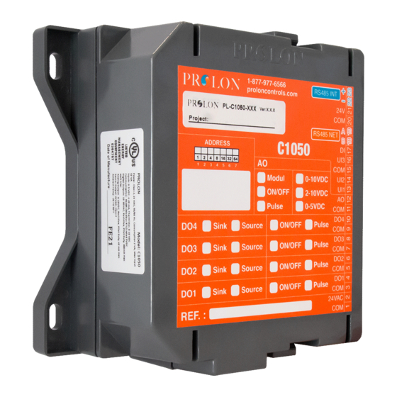
Components Component Identification 24VAC BIAS THERM BIAS THERM Figure 1 - Component Identification Legend: A - Analog Input Signal Mode Jumpers B - Addressing dipswitch C - Jumpers for terminating and bias resistors for the INT port (see I) D - Jumpers for terminating and bias resistors for the NET port (see K) E - SOURCE/SINK dipswitch for Output 4 F - SOURCE/SINK dipswitch for Output 3 G - SOURCE/SINK dipswitch for Output 2... -
Page 7: Leds
The example on Figure 3 shows the switches 1, 2 and 4 on the ON position. So the corresponding values are 1, 2 and 8, giving an address sum of 11. (1+2+8=11) The Prolon network allows a maximum of 127 addresses, therefore 127 controllers. Figure 3 - Addressing Dipswitches... -
Page 8: Input And Output Identification
The C1050 Humidity Controller has 2 separate communication ports offering the same functionality on each. Both act as ports for incoming Modbus communications from other Prolon devices or interfaces, such as a Network Controller or remote computer with Prolon Focus software. -
Page 9: Inputs
Inputs Analog Input The C1050 series controllers are equipped with three general purpose analog inputs. These inputs can be configured to receive signals of the following types: • Thermistor (Ω) • 0-5V • 4 -20mA • 0-10V When a thermistor is used, the thermistor must be 10KΩ TYPE 3. -
Page 10: Relative Humidity Sensors
Relative Humidity Sensors The C1050 Humidity controller has two inputs dedicated the relative humidity readings in the room (or return duct) and the supply (optional). This information is then integrated into its control sequences. The sensors used must provide a 0-5VDC signal. -
Page 11: Outputs
(Output 4 and Output 5). Output 4 is an ON-OFF triac output and Output 5 is an analog 0-10VDC modulating or pulsing output, which follows a proportional and integral algorithm (PI). This PI function is fully customizable via the Prolon Focus software. -
Page 12: Typical Connection Of The Triac Outputs 3 And 4
2) Switch position to obtain a SINK passive output: Switch for Output 4 Isolated dry contact (On/O ) Figure 10 - Output in SINK mode Typical Connection of the Triac Outputs 3 and 4 Two types of configurations are possible: 1) Active output (SOURCE). -
Page 13: Typical Connection Of The Analog Output
Typical Connection of the Analog Output Two types of configuration are possible: 1) The C1050 powers the load and provides a control signal: 24 VAC power (From terminal block #2 of the controller) Controlled 0-10v Load Figure 13 - Connecting the Analog Output (Controller Powered) 2) The C1050 only provides the control signal to the load, which is powered by an external source: External 24 VAC... -
Page 14: Power Source / Network
Power Source The Prolon C1050 controller is powered by a 24 VAC power source connected using the "COM" terminal and the "24 VAC" terminal. The common for all inputs and outputs are the same as the power source’s common (exception: when an out- put is set to passive, the common for this output will not correspond to the power source common). -
Page 15: Technical Specifications
Certification: UL916 Energy Management Equipment, CAN/CSA-C22.2, RoHS, FCC part 15: 2012 class B The performance specifications are nominal and conform to acceptable industry standards. Prolon Inc. will not be liable for damages resulting from misapplication or misuse of its products. -
Page 16: Compliance
Caution: Any changes or modifications not approved by Prolon can void the user’s authority to operate the equipment. Note: This equipment has been tested and found to comply with the limits for a Class B digital device, pursuant to part 15 of the FCC Rules. -
Page 17: Overall Dimensions
No part of this document may be photocopied or reproduced by any means, or translated to another language without prior written consent of Prolon. All specifications are nominal and may change as design improvements are introduced. Prolon shall not be liable for damages resulting from misapplication or misuse of its products.
Need help?
Do you have a question about the C1050 Series and is the answer not in the manual?
Questions and answers