Prolon C1050 Series Specifications And Operational Manual
Rooftop controller
Hide thumbs
Also See for C1050 Series:
- Hardware manual (17 pages) ,
- Technical reference manual (98 pages) ,
- Hardware manual (17 pages)

Related Manuals for Prolon C1050 Series


Summary of Contents for Prolon C1050 Series
- Page 1 HARDWARE GUIDE Rooftop Controller C1050 Series Specifications and Operational Guide www.proloncontrols.com | info@proloncontrols.com 17 510, rue Charles, Suite 100, Mirabel, QC, J7J 1X9 REV. 7.3.0 PL-HRDW-RTU-C1050-C/F-EN...
-
Page 2: Table Of Contents
Table of Contents General Information ............................... 4 PL-C1050 Basic Rooftop Controller ................................4 Description ..........................................4 General Behaviour ......................................4 Operating Sequence ............................... 5 General ...........................................5 Occupied Mode ........................................5 Unoccupied Mode ......................................5 Components ..................................6 Component Identification ....................................6 LEDs ............................................7 Address Configuration for Networking ..............................7 Input and Output Identification ..................................8 Inputs .................................... - Page 3 Table of Figures Figure 1 - Component Identification..................................6 Figure 2 - LEDs Identification ....................................7 Figure 3 - Addressing Dipswitches ..................................7 Figure 4 - Input and Output Identification ...............................8 Figure 5 - Analog input ......................................9 Figure 6 - Connecting the Sensors ..................................9 Figure 7 - Night Setback Contact Conection ..............................
-
Page 4: General Information
Description The Prolon C1050 Basic Rooftop is a microprocessor-based controller designed to operate rooftops or other mechanical HVAC systems. It acts as a master when used on a network with other Prolon zone controllers. General Behaviour Although fully programmable, the Prolon C1050 Basic Rooftop controller uses pre-established control sequences or ’’profiles’’... -
Page 5: Operating Sequence
General The Prolon C1050 Basic Rooftop controller receives readings from three temperature sensors located outside, in the re- turn duct and in the supply duct. Also, as a Master device, it receives data from the zone controllers sent on the network bus. -
Page 6: Components
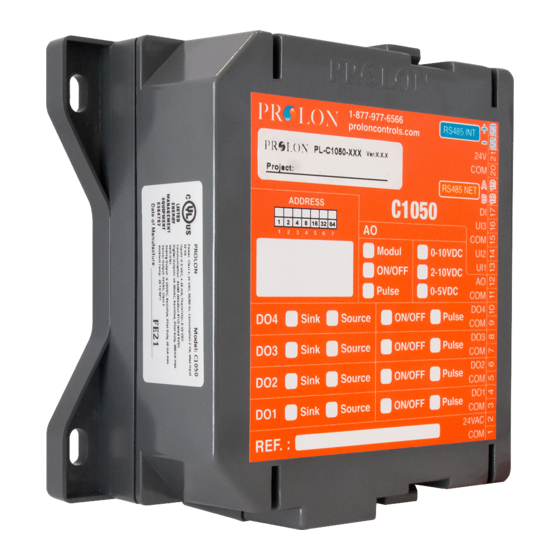
Components Component Identification 24VAC BIAS THERM BIAS THERM Figure 1 - Component Identification Legend: A - Analog Input Signal Mode Jumpers B - Addressing dipswitch C - Jumpers for terminating and bias resistors for the INT port (see I) D - Jumpers for terminating and bias resistors for the NET port (see K) E - SOURCE/SINK dipswitch for Output 4 F - SOURCE/SINK dipswitch for Output 3 G - SOURCE/SINK dipswitch for Output 2... -
Page 7: Leds
The example on Figure 3 shows the switches 1, 2 and 4 on the ON position. So the corresponding values are 1, 2 and 8, giving an address sum of 11. (1+2+8=11) The Prolon network allows a maximum of 127 addresses, therefore 127 controllers. Figure 3 - Addressing Dipswitches... -
Page 8: Input And Output Identification
The C1050 Rooftop Controller has two separate communication ports offering the same functionality on each. Both act as ports for incoming Modbus communications from other Prolon devices or interfaces, such as a Network Controller or remote computer with Prolon Focus software. -
Page 9: Inputs
Inputs Analog Input The C1050 series controllers are equipped with three general purpose analog inputs. These inputs can be configured to receive signals of the following types: • Thermistor (Ω) • 0-5V • 4 -20mA • 0-10V When a thermistor is used, the thermistor must be 10KΩ TYPE 3. -
Page 10: Occupancy Mode (Night Setback)
Occupancy Mode (Night Setback) Temperature setback savings can be obtained by using a dry contact originating from an external timer to switch the controller from occupied to unoccupied mode. The timer contact used must be connected to the "OCC" and the "GND" terminals. -
Page 11: Outputs
The C1050 Basic Rooftop controller contains 5 customizable outputs, 4 being Triac type switch outputs and one being 0-10Vdc analog modulating / pulsed / On-or-Off output. Some outputs are configurable and follow a proportional and integral algorithm (PI) to ensure precise adjustment of the device. All configurations are performed via the Prolon Focus software. -
Page 12: Typical Connection Of The Triac Outputs 1 Through 4
Typical Connection of the Triac Outputs 1 through 4 On the C1050 Rooftop controller, all triac outputs must be set to SOURCE mode because they all share a single source supply: the equipment’s transformer. All triac outputs have a SOURCE / SINK configuration switch; they must be set to “SWITCH”... -
Page 13: Dmux-4J Connection On Output 2 For Stage 3 Or 4 Cooling
DMUX-4J Connection on Output 2 for Stage 3 or 4 Cooling When 3 or 4 stages of cooling are required, the C1050 Rooftop controller must be equipped with a DMUX-4J. The DMUX- 4J input is only connected to Output 2 on the C1050 Rooftop controller. The DMUX-4J must be configured to “Sequenced Relay Control”... -
Page 14: Pta2 Connection On Output 2 For Analog Cooling
PTA2 Connection on Output 2 for Analog Cooling When analog cooling is required, the C1050 Rooftop controller must be equipped with a PTA2 v.1. The PTA2 input is connected to Output 2 on the C1050 Rooftop controller. The input pulse range must be set to 0.1-10 sec. For more infor- mation on the PTA2, consult the Specification Sheet and the Installation Guide for the PTA2. -
Page 15: Power Source & Network
Figure 13 - Connecting the 24VAC Power Source Network Communication The Prolon C1050 Rooftop controller is primarily designed to work with Prolon zone controllers. When they are networked the Rooftop and zone controllers all communicate in real-time. The network connections are made using the network terminal blocks located on the C1050 controller. -
Page 16: Technical Specifications
Certification: UL916 Energy Management Equipment, CAN/CSA-C22.2, RoHS, FCC part 15: 2012 class B The performance specifications are nominal and conform to acceptable industry standards. Prolon Inc. will not be liable for damages resulting from misapplication or misuse of its products. -
Page 17: Compliance
Caution: Any changes or modifications not approved by Prolon can void the user’s authority to operate the equipment. Note: This equipment has been tested and found to comply with the limits for a Class B digital device, pursuant to part 15 of the FCC Rules. -
Page 18: Overall Dimensions
No part of this document may be photocopied or reproduced by any means, or translated to another language without prior written consent of Prolon. All specifications are nominal and may change as design improvements are introduced. Prolon shall not be liable for damages resulting from misapplication or misuse of its products.
Need help?
Do you have a question about the C1050 Series and is the answer not in the manual?
Questions and answers