Prolon C1000 Series Hardware Manual
Rooftop controller
Hide thumbs
Also See for C1000 Series:
- Hardware manual (23 pages) ,
- Quick start manual (10 pages) ,
- Operational manual (19 pages)
Table of Contents
Advertisement
Quick Links
Download this manual
See also:
Hardware Manual
Advertisement
Table of Contents

Related Manuals for Prolon C1000 Series


Summary of Contents for Prolon C1000 Series
- Page 1 HARDWARE GUIDE Rooftop Controller C1000 Series Specifications and Operational Guide www.proloncontrols.com | info@proloncontrols.com 17 510, rue Charles, Suite 100, Mirabel, QC, J7J 1X9 REV. 6.1.6 PL-HRDW-RTU-C1000-C/F-EN...
-
Page 2: Table Of Contents
Table of Contents General Information ..........................4 PL-C1000 Basic Rooftop Controller........................... 4 Description ..................................4 General Behaviour ................................ 4 Operating Sequence ..............................5 General .................................... 5 Occupied Mode ................................5 Unoccupied Mode ................................ 5 Components ............................6 Component Identification ............................6 LEDs .................................... - Page 3 Table of Figures Figure 1 - Component Identification ..........................6 Figure 2 - LEDs Identification ............................7 Figure 3 - Addressing Dipswitches ..........................7 Figure 4 - RJ45 Jumper ..............................8 Figure 5 - Input and Output Identification ........................8 Figure 6 - RJ45 Pinout ................................
-
Page 4: General Information
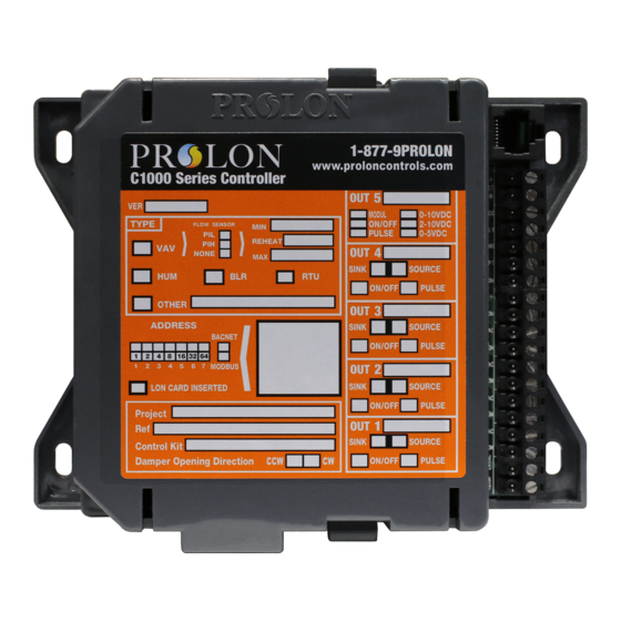
PL-C1000 Basic Rooftop Controller Description The ProLon C1000 Basic Rooftop is a microprocessor-based controller designed to operate rooftops or other mechanical HVAC systems. It acts as a master when used on a network with other ProLon zone controllers. General Behaviour Although fully programmable, the ProLon C1000 Basic Rooftop controller uses pre-established control sequences or ’’profiles’’... -
Page 5: Operating Sequence
Operating Sequence General The ProLon C1000 Basic Rooftop controller receives readings from three temperature sensors located outside, in the return duct and in the supply duct. Also, as a Master device, it receives data from the zone controllers sent on the network bus. A dry contact originating from an external timer signals the occupancy status (optional) to the Master. -
Page 6: Components
Components Component Identification BIAS TERM BIAS TERM Figure 1 - Component Identification Legend: A - Addressing Dipswitch B - Output 1 Dipswitch C - Output 2 Dipswitch D - Output 3 Dipswitch E - Output 4 Dipswitch F - Master reset button G - Terminal Blocks for Inputs and Outputs H - LEDs I - Jumpers for terminating and bias resistors for the NET port... -
Page 7: Leds
The example in Figure 3 shows the switches 1, 2 and 4 in the ON position. Therefore, the corresponding values are 1, 2 and 8, giving an address sum of 11. The ProLon network allows a maximum of 127 addresses, therefore 127 controllers. Figure 3 - Addressing Dipswitches... -
Page 8: Jumper To Supply Power To The Rj45 Plug
The RJ45 connector allows the use of premade CAT5 cables for simple plug-and-play RS485 communication. This RJ45 connector follows the Modbus pinout specification for RS485 communication. RTUS INT Port: Incoming RS485 INT Port: ProLon Digital Temperature Sensor - OR - Incoming RS485 Network communication (Modbus) -
Page 9: Inputs
Inputs Temperature Sensors The C1000 Rooftop controller has three analog inputs that monitor outside air, return air and supply air temperatures (see Figure 7) and will integrate these readings into its control sequence. The sensors used are standard 10k type 3 thermistors that share a single common connection. Alternatively, the supply air temperature can be retrieved from a zone controller that has its own supply sensor and belongs to the C1000’s network. -
Page 10: Occupancy Mode (Night Setback)
Occupancy Mode (Night Setback) Temperature setback savings can be obtained by using a dry contact originating from an external timer to switch the controller from occupied to unoccupied mode. The timer contact used must be connected to the "OCC" and the "GND" terminals (see Figure 8). To indicate occupied mode, the contact must be open. To indicate unoccupied mode, the contact must be closed. -
Page 11: Outputs
(PI) to ensure precise adjustment of the device. All configurations are performed via the ProLon Focus software. An integrated resettable fuse protects each of the outputs of the C1000 against current surges and short circuits. -
Page 12: Typical Connection Of The Triac Outputs 1 Through 4
Typical Connection of the Triac Outputs 1 through 4 On the C1000 Rooftop controller, all triac outputs must be set to SOURCE mode because they all share a single source supply: the equipment’s transformer. All triac outputs have a SOURCE / SINK configuration switch;... -
Page 13: Dmux-4J Connection On Output 2 For Stage 3 Or 4 Cooling
DMUX-4J Connection on Output 2 for Stage 3 or 4 Cooling When 3 or 4 stages of cooling are required, the C1000 Rooftop controller must be equipped with a DMUX-4J. The DMUX-4J input is only connected to Output 2 on the C1000 Rooftop controller. The DMUX-4J must be configured to “Sequenced Relay Control”... -
Page 14: Pta2 Connection On Output 2 For Analog Cooling
PTA2 Connection on Output 2 for Analog Cooling When analog cooling is required, the C1000 Rooftop controller must be equipped with a PTA2 v.1. The PTA2 input is connected to Output 2 on the C1000 Rooftop controller. The input pulse range must be set to 0.1-10 sec. -
Page 15: Power Source & Network
Figure 14 - Connecting the 24VAC Power Source Network Communication The ProLon C1000 Rooftop controller is primarily designed to work with ProLon zone controllers. When they are networked the Rooftop and zone controllers all communicate in real-time. The network connec- tions are made using the network terminal blocks located on the C1000 controller (see Figure 15). -
Page 16: Technical Specifications
Environment: 32-122 ºF (0-50 ºC) Non-Condensing Certification: RoHS, FCC part 15: 2012 class B The performance specifications are nominal and conform to acceptable industry standards. ProLon Inc. will not be liable for damages resulting from misapplication or misuse of its products. -
Page 17: Compliance
(1) this device may not cause harmful interference, and (2) this device must accept any interference re- ceived, including interference that may cause undesired operation. Caution: Any changes or modifications not approved by ProLon can void the user’s authority to operate the equipment. -
Page 18: Overall Dimensions
No part of this document may be photocopied or reproduced by any means, or translated to another language without prior written consent of ProLon. All specifications are nominal and may change as design improvements are introduced. ProLon shall not be liable for damages resulting from misapplication or misuse of its products.
Need help?
Do you have a question about the C1000 Series and is the answer not in the manual?
Questions and answers