Prolon M2000 Series Hardware Manual
Chiller controller
Hide thumbs
Also See for M2000 Series:
- Hardware manual (21 pages) ,
- Quick start manuals (16 pages) ,
- Technical reference manual (98 pages)

Subscribe to Our Youtube Channel
Related Manuals for Prolon M2000 Series


Summary of Contents for Prolon M2000 Series
- Page 1 HARDWARE GUIDE Chiller Controller M2000 Series Specifications and Operational Guide www.proloncontrols.com | info@proloncontrols.com 17 510, rue Charles, Suite 100, Mirabel, QC, J7J 1X9 REV. 7.3.4 PL-HRDW-CHL-M2000-C/F-EN...
-
Page 2: Table Of Contents
Table of Contents General Information ............................... 4 PL-M2000 Chiller Controller ....................................4 Description ..........................................4 General Behavior ........................................4 Operating Sequence ............................... 5 Pump ............................................5 Water Supply Setpoint ......................................5 Chiller Stages ........................................5 Pressure Control ........................................5 Components ..................................6 Component Identification ....................................6 LEDs and Switches ......................................7 HAND/OFF/AUTO Switches .....................................8 Jumpers ..........................................8 Input and Output Identification ..................................9... - Page 3 Table of Figures Figure 1 - Component Identification ..................................6 Figure 2 - LEDs Identification ....................................7 Figure 3 - Location of the EXTERNAL jumpers ...............................8 Figure 4 - Location of the INTERNAL jumpers ..............................8 Figure 5 - INT and NET jumpers ...................................8 Figure 6 - AI jumpers ........................................8 Figure 7 - RJ45 Pinout ......................................9 Figure 8 - Input and Output Identification ...............................9...
-
Page 4: General Information
The various programming options allow the user to incorporate lead-lag sequences into the pumps and chiller stages, specify conditions for pump activity as well as apply schedules and limits. All these parameters can be accessed and modified using the Prolon Focus software. -
Page 5: Operating Sequence
Operating Sequence Pump The PL-M2000 Chiller Controller can control systems with one or two pumps. The dual pump sequence is intended for hydronic systems where there is a secondary pump that acts as a backup to the primary pump, with both pumps being installed in parallel. -
Page 6: Components
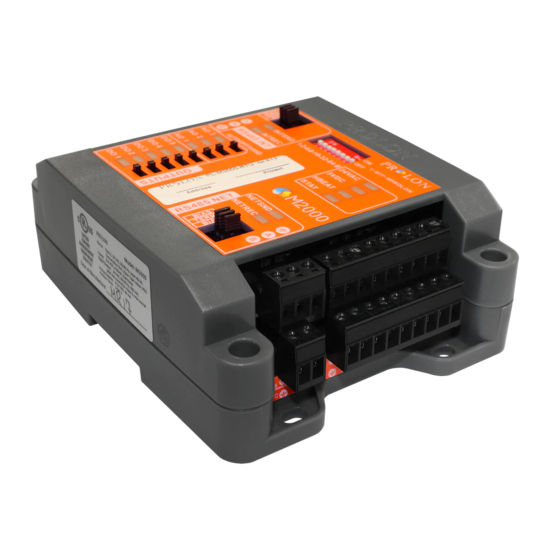
Components Component Identification Figure 1 - Component Identification Legend: A - Addressing Dipswitch B - AUTO/OFF/HAND Switches C - RS485 INT port for interface communication (RJ45 plug and screw connectors are in parallel) D - Analog outputs (3) E - Digital outputs (5) F - Analog inputs (9) G - RS485 NET port for network communication H - Terminal block for 24VAC (Class 2 transformer) -
Page 7: Leds And Switches
When this LED is ON and steady, the M2000 is inactive present on analog output 1. and the microchip is awaiting programming (you must use Prolon’s Focus software to reprogram the • DO5: Represents the activity of digital output 5. microchip). -
Page 8: Hand/Off/Auto Switches
• INT: These are the jumpers for the bias and terminating resistors used for the interface communication bus. See the Prolon network guide for information about bias and terminating resistors. (See Figure 5) • NET: These are the jumpers for the bias and terminating resistors used for the network communication bus. See the Prolon network guide for information about bias and terminating resistors. -
Page 9: Input And Output Identification
The M2000 Chiller Controller has 2 separate communication ports offering the same functionality on each. Both act as ports for incoming Modbus communications from other Prolon devices or interfaces, such as a Network Controller or remote computer with Prolon Focus software. -
Page 10: Addressing Dipswitch Configuration For Network Communication
The example in Figure 9 shows the switches 1, 2 and 4 in the ON position. Therefore, the corresponding values are 1, 2 and 8, giving an address sum of 11. The Prolon network allows a maximum of 127 addresses; therefore 127 controllers. Figure 9 - Addressing Dipswitch... -
Page 11: Inputs
Inputs Temperature Sensors The M2000 Chiller Controller has five analog inputs to monitor various temperature readings, including outside air, supply water, return water, entering condenser water (ECWT) and leaving condenser water (LCWT) temperatures. The sensors used are standard 10k type 3 thermistors that share a single common connection (see Figure 10). Note that the outside air temperature can be also be provided by an alternate source. -
Page 12: Water Pressure
Water Pressure Analog Input 8 on the M2000 Chiller Controller is dedicated to a water pressure sensor. The M2000 accepts various input signal voltages including 0-5VDC, 1-5VDC and 0.5-4.5VDC. Additionally, it can accept current-based signals as well, including 4-20mA and 0-20mA, but the internal jumpers first need to be set in the correct mode for current sensing (see Jumpers section). -
Page 13: Outputs
The M2000 Chiller controller contains 8 customizable outputs; five triac ON/OFF outputs (24VAC) and three analog outputs (0-10VDC). Output configuration is performed via the Prolon Focus software. An integrated resettable fuse protects each of the outputs of the M2000 against current surges and short circuits. This protection will cut the current to the output as soon as an overload condition is detected. -
Page 14: Typical Connection Of Triac Outputs 1 To 5
Typical Connection of Triac Outputs 1 to 5 On the M2000 Chiller controller, all triac outputs produce a 24 VAC live voltage when activated. Note that all output voltages originate from a single voltage supply: the equipment’s transformer. Consequentially, only the live side of the output connections are usually needed;... -
Page 15: Power Source & Network
Figure 16 - Connecting the 24VAC Power Source Network Communication The Prolon M2000 Chiller controller is designed to work standalone or networked with Prolon master controllers. When networked, the master transmits the occupancy status, outside temperature and math demand in real-time. The network connections are made using the network terminal block located on the M2000 controller (see Figure 17). -
Page 16: Technical Specifications
Certification: UL916 Energy Management Equipment, CAN/CSA-C22.2, RoHS, FCC part 15: 2012 class B The performance specifications are nominal and conform to acceptable industry standards. Prolon Inc. will not be liable for damages resulting from misapplication or misuse of its products. -
Page 17: Compliance
Caution: Any changes or modifications not approved by Prolon can void the user’s authority to operate the equipment. Note: This equipment has been tested and found to comply with the limits for a Class B digital device, pursuant to part 15 of the FCC Rules. -
Page 18: Overall Dimensions
No part of this document may be photocopied or reproduced by any means, or translated to another language without prior written consent of Prolon. All specifications are nominal and may change as design improvements are introduced. Prolon shall not be liable for damages resulting from misapplication or misuse of its products.
Need help?
Do you have a question about the M2000 Series and is the answer not in the manual?
Questions and answers