Table of Contents
Advertisement
Quick Links
Advertisement
Table of Contents

Related Manuals for Datavideo TLM-170V


Summary of Contents for Datavideo TLM-170V
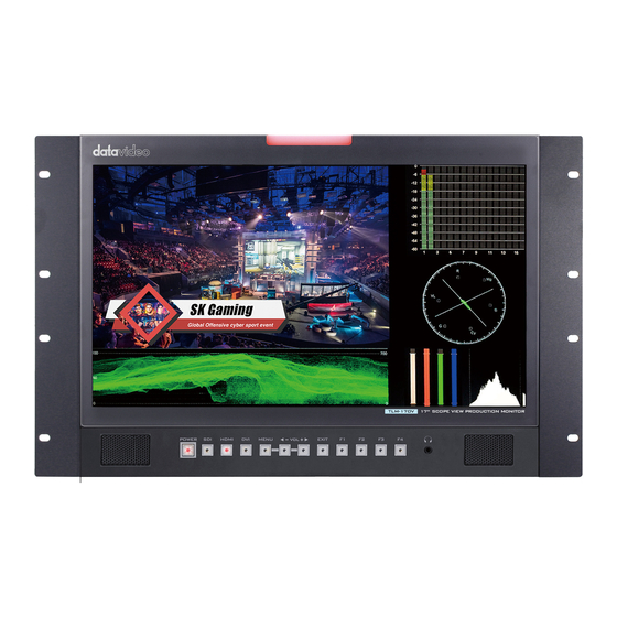
- Page 1 17.3” SCOPEVIEW PRODUCTION MONITOR TLM-170V Instruction Manual...
-
Page 2: Table Of Contents
Table of Contents FCC COMPLIANCE STATEMENT......................4 WARNINGS AND PRECAUTIONS ..................... 4 WARRANTY ............................. 5 ........................5 TANDARD ARRANTY ........................5 HREE ARRANTY DISPOSAL ............................6 1. INTRODUCTION ........................7 ............................7 EATURES ..........................7 ODEL YPES ....................8 OMPATIBLE ESOLUTIONS AND ORMATS 2. - Page 3 Datavideo Technologies will try to give correct, complete and suitable information. However, Datavideo Technologies cannot exclude that some information in this manual, from time to time, may not be correct or may be incomplete. This manual may contain typing errors, omissions or incorrect information.
-
Page 4: Fcc Compliance Statement
AC adapter. If you are not sure of the type of power available, consult your Datavideo dealer or your local power company. 8. Do not allow anything to rest on the power cord. Do not locate this unit where the power cord will be walked on, rolled over, or otherwise stressed. -
Page 5: Warranty
State Drive, SD Card, USB Thumb Drive, Lighting, Non-PCIe Card and third party provided PC components are covered for 1 year. The three-year warranty must be registered on Datavideo's official website or with your local Datavideo office or one of its authorized distributors within 30 days of purchase. -
Page 6: Disposal
Disposal For EU Customers only - WEEE Marking This symbol on the product or on its packaging indicates that this product must not be disposed of with your other household waste. Instead, it is your responsibility to dispose of your waste equipment by handing it over to a designated collection point for the recycling of waste electrical and electronic equipment. -
Page 7: Introduction
The TLM-170V features 1920x1080 full HD resolutions and 170° wide viewing angle for outstanding viewing experience. The TLM-170V includes various built-in functions such as waveform, vector scope and SDI/HDMI cross converter. Because of its portability, the TLM-170V can be flexibly installed in OB Van, satellite truck and central control room. Features ... -
Page 8: Compatible Resolutions And Formats
Compatible Resolutions and Formats TLM-170V Interface Resolutions and Formats HDMI 1920x1080P @ 59.94 ᴠ ᴠ 1920x1080P @ 60 ᴠ ᴠ 1920x1080P @ 50 ᴠ ᴠ 1920x1080P @ 29.97 ᴠ ᴠ 1920x1080P @ 25 ᴠ ᴠ 1920x1080P @ 30 ᴠ ᴠ... -
Page 9: Connections And Controls
Buttons Descriptions Power ON/OFF This button powers the monitor ON/OFF. The main power switch is located at the rear of the TLM-170V. SDI Button The SDI video source is enabled when the LED indicator is turned HDMI 1/2 Button The HDMI video source is enabled when the LED indicator is turned ON. - Page 10 MENU Button Press the MENU button to open the OSD menu. Once in the OSD menu, press the MENU button to make a selection. Audio Volume Adjustment Buttons Once in the OSD menu, navigate the menu or increase/decrease parameter values using the audio volume adjustment buttons. While NOT in the OSD menu, pressing either one of the audio volume adjustment buttons will open a Volume slide bar at the bottom of the screen.
- Page 11 3. Move down to the RESET option which is selected by pressing the MENU button. 4. Press either the VOL+ or VOL- button to enable the reset. Note: The reset function resets all TLM-170V settings. Headphone Jack Once the 3.5mm headphone jack is connected, the internal...
-
Page 12: Rear Panel
USB Port DC IN 12V ON/OFF Switch Ports Descriptions Tally light input socket can be used to connect Datavideo’s RMC 3.5mm Tally Light Input or TB series devices as well as the intercom system’s beltpack. HDMI Output HDMI video output HDMI Input 1/2 Connects HDMI video and audio source devices. -
Page 13: Osd Menu
OSD MENU The TLM-170V can be set up using an OSD menu system. To display the OSD menu press the MENU button. This menu system is navigated using the Left / Right buttons. The Left / Right buttons are also used to change parameter values. Press the MENU button to select an option and the EXIT button to close the OSD menu. - Page 14 2.35:1 Safety Market Green Marker Color Blue White Black Marker Mat Thickness Zoom Scan Aspect Pixel to Pixel Full 16:9 1.85:1 Aspect 2.35:1 Function Underscan H/V Delay Check Field Green Blue...
- Page 15 Zoom Freeze DSLR Multi Waveform YCbCr Waveform Trans. Peaking Green Waveform Peaking Color Blue White Peaking Level 0 – 100 False Color Exposure Exposure Level 0 – 100 Histogram Color Volume 0 – 100 Audio Level Meter Chinese Language English HDMI/SDI Convert System Color Bar...
-
Page 16: Picture
Standby Reset Picture The TLM-170V allows you to adjust the basic image settings such as the brightness, contrast, saturation, tint and sharpness. Advanced settings are HDMI RGB range, color space, gamma correction, back light mode, back light level, and color temperature. -
Page 17: Gamma
Back Light Adjust the back light level from 0 – 100. Color Temperature Select a color temperature for your scene. Color temperatures available on the TLM-170V are listed as follows: 5500°K (Desktop publishing or printing) 6500°K (Usually for ordinary PC use) ... -
Page 18: Center Marker
170V’s aspect marker (a.k.a. guide frame) so that you can record the entire screen while still knowing where the cut-off will be by putting a mat over it. Center Marker The Center Marker, if turned on, will place a crosshair in the middle of the screen. Aspect Marker Sets the aspect marker display at the aspect ratio selected from the list below: ... -
Page 19: Marker Color
This sets the aspect marker thickness ranging from 1 to 7. Function This allows the user to set advanced settings for the TLM-170V, such as the scan mode, the aspect ratio, underscan mode, H/V delay, check field, zoom, and etc. Details of how these functions can be... -
Page 20: Underscan
Underscan If enabled, the image rendered on the display will be smaller than the physical area of the screen. This creates a border around the image. H/V Delay Used to monitor the Blanking area for H sync and V sync. In H delay mode, the horizontal sync is delayed so that the horizontal blanking period is displayed on the screen. -
Page 21: Check Field
Freeze The monitor’s screen freezes once enabled. DSLR This option is useful if Canon 5D2 or 5D3 cameras are connected to the TLM-170V. Waveform The TLM-170V also allows the user to display the image alongside with different monitoring waveforms such as the waveform, vector scope, histogram and audio level meter. -
Page 22: Waveform
Waveform The TLM-170V offers users different waveform options listed as follows: Muilt (Vector scope, YCbCr waveform monitoring, histogram and audio meter) Y (Y Waveform monitoring) YCbCr (YCbCr Waveform monitoring) RGB (RGB Waveform monitoring and histogram) Off Note: If Waveform is set to Multi, the Histogram is enabled by default. -
Page 23: Waveform Trans
This function works well if the subject of the focus is correctly exposed for high contrast. Red, Green, Blue and White are the four available outline colors on the TLM-170V. The Peaking Level determines the sensitivity of the filter. Setting the peaking level to a high value means more areas will be highlighted including lower contrast areas. -
Page 24: Exposure
For example, areas with exposure level of 56IRE when applied the false color will be shown as pink color on the monitor. Therefore, as you increase the exposure, that area will change color to grey, then yellow and finally to red if overexposed. Blue indicates underexposure. An example of an original image with the false color applied is shown on the left of the image below. -
Page 25: Histogram
Histogram The histogram is a great tool that helps you to improve the overall exposure of the image. The Y or luminosity histogram is a graph that describes the human-eye perceived brightness distribution within an image. To produce the luminosity histogram, first break an image into individual pixels, then each pixel is converted so that it becomes a luminosity based on a weighted average of the three colors at that pixel. - Page 26 RGB histogram. On the TLM-170V, the RGB histogram is shown with the color overlay as depicted in the diagram below.
-
Page 27: Audio
The Volume option sets the audio level of the input video, which can be viewed visually on the TLM-170V by enabling the Embedded Audio Level Meter. Note: If the monitor is in SDI mode, you will see 16 channels; in HDMI mode, there will only be 2 channels. -
Page 28: Color Bar
Note: Once the HDMI/SDI Convert is disabled, the input will be delivered to its corresponding output interface. Therefore the HDMI IN video will only be shown on the monitor connected to the HDMI OUT and the SDI IN video will only be shown on the monitor connected to the SDI OUT. Color Bar Available options are listed as follows: OFF: disables the color bar... -
Page 29: Color Calibration
Color Calibration To use this feature, you will need an additional purchase of Lightillusion’s LightSpace Color Management System (CMS) which includes a calibration probe and CMS software. The TLM-170V works with CAL, PRO and XPT versions only. Visit https://www.lightillusion.com/lightspace.html. See the CMS Color Calibration Process in the subsequent chapter. -
Page 30: Color Management System - Calibration Process
Color Management System – Calibration Process This Chapter will introduce the use of Lightillusion's CMS software for color correction. Before starting the calibration process, you need to install and register the CMS software first. Connect the calibration device to the PC or the laptop then install its driver. After the calibration environment has been properly set up, follow the steps below to start color calibrating your monitor. - Page 31 4. Connect the TLM-170V monitor Connect the TLM-170V to the HDMI port of your PC or laptop, power ON the monitor and set the computer output to the extended output mode. Then open the graphics control panel and set the PC’s HDMI output to RGB full-range.
- Page 32 30 minutes. 7. Enable color calibration mode on the TLM-170V monitor. Open the TLM-170V’s OSD menu, then go to System Color Calibration and select ON. 8. Luminance calibration (adjust the backlight). On the LightSpace CMS UI, click Tools Calibration Display Characterization to open the Display Characterization window.
- Page 33 OK button in the dialogue box to start calibration. Repeat the process until the MAX value in the Luminance Units pane is in the range of 80 – 120. Note that the closer the MAX value to 100, the better the TLM-170V is calibrated.
- Page 34 Click the Measure button, the Calibration Status window will appear along with the Calibration Area and a dialogue box. Drag the Calibration Area onto the TLM-170V. Finally enter a name for this particular calibration in the dialogue box, point the probe at the calibration area as close as possible then click the OK button to start calibration.
- Page 35 10. Create a 3D Cube Color Calibration File Click Tools Colour Space Convert Colour Space to open the Convert Colour Space window. In the Source and Destination panes, select Rec709 for the color space. In the Name textbox enter the name of the 3D cube color calibration file.
- Page 36 Rename the exported 3D cube file to “lcd.cube” and save it on a USB thumb drive. Insert the USB thumb into the SERVICE port of the TLM-170V and you will be prompted whether to write the 3D CUBE file to the monitor. The color calibration process is complete after the 3D CUBE file has been...
-
Page 37: Firmware Update
Firmware Update Datavideo usually releases new firmware containing new features or reported bug fixes from time to time. Customers can either download the TLM-170V firmware as they wish or contact their local dealer or reseller for assistance. This section outlines the firmware upgrade process which should take approximately 20 minutes to complete. -
Page 38: Dimensions
Dimensions All measurements in millimeters (mm) -
Page 39: Specifications
Specifications Size 17.3'' Resolution 1920 x 1080 Contrast Ratio 700:1 View Angle 178° (Horizontal) / 178° (Vertical) (Typ.) Brightness 300 cd/m HDMI x 2 Video Input SDI x 1 HDMI x 1 Video Output SDI x 1 1920x1080p 50/59.94/60 1920x1080p 23.98/23.98sf/24/24sf/25/25sf/29.97/29.97sf/30/30sf 1920x1080i 50/59.94/60 SDI Video Format 1280x720p 23.98/24/25/29.97/30/50/59.94/60... -
Page 40: Service And Support
Jun-06.2019 Version E2...
Need help?
Do you have a question about the TLM-170V and is the answer not in the manual?
Questions and answers