
Related Manuals for Datavideo TLM-170K


Summary of Contents for Datavideo TLM-170K
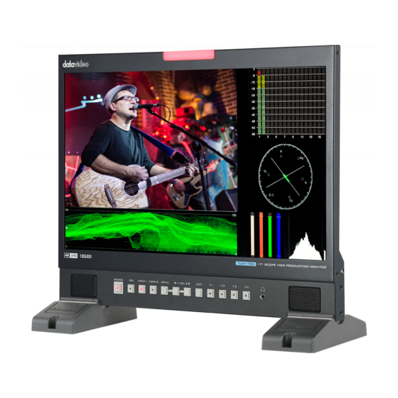
- Page 1 17” SCOPEVIEW PRODUCTION MONITOR TLM-170K / TLM-170KM / TLM-170KR Instruction Manual...
-
Page 2: Table Of Contents
Table of Contents FCC COMPLIANCE STATEMENT ......................4 WARNINGS AND PRECAUTIONS ....................... 4 WARRANTY ............................. 5 ..........................5 TANDARD ARRANTY ..........................5 HREE ARRANTY DISPOSAL ............................6 1. INTRODUCTION ......................... 7 ..............................7 EATURES ............................. 7 ODEL YPES 2. CONNECTIONS AND CONTROLS ....................8 .............................. - Page 3 Datavideo Technologies will try to give correct, complete and suitable information. However, Datavideo Technologies cannot exclude that some information in this manual, from time to time, may not be correct or may be incomplete. This manual may contain typing errors, omissions or incorrect information.
-
Page 4: Fcc Compliance Statement
AC adapter. If you are not sure of the type of power available, consult your Datavideo dealer or your local power company. 8. Do not allow anything to rest on the power cord. Do not locate this unit where the power cord will be walked on, rolled over, or otherwise stressed. -
Page 5: Warranty
State Drive, SD Card, USB Thumb Drive, Lighting, Non-PCIe Card and third party provided PC components are covered for 1 year. The three-year warranty must be registered on Datavideo's official website or with your local Datavideo office or one of its authorized distributors within 30 days of purchase. -
Page 6: Disposal
Disposal For EU Customers only - WEEE Marking This symbol on the product or on its packaging indicates that this product must not be disposed of with your other household waste. Instead, it is your responsibility to dispose of your waste equipment by handing it over to a designated collection point for the recycling of waste electrical and electronic equipment. -
Page 7: Introduction
Introduction The TLM-170K offers a UHD 3840 x 2160 LCD Panel which provides a wide viewing angle of 178°, 300 cd/m² brightness, and 1000:1 contrast ratio. It features a 12G SDI input and two HDMI 2.0 inputs with one loop through output allowing connection of up to DCI 4K and Ultra HD video sources. -
Page 8: Connections And Controls
Descriptions Power ON/OFF This button powers the monitor ON/OFF. The main power switch is located at the rear of the TLM-170K. SDI Button Press once to enable the SDI video source on the monitor screen. You can connect the loop thru port (see... - Page 9 HDMI 1/2 Button Press once to enable the HDMI video source on the monitor screen. Please note that the two video sources cannot be enabled at the same time. You can connect the loop thru port (see Rear Panel) to a monitor to view the activated input video source.
- Page 10 2. Press the MENU button to enter the SYSTEM sub menu. 3. Move down to the RESET option which is selected by pressing the MENU button. 4. Press either the VOL+ or VOL- button to enable the reset. Note: The reset function resets all TLM-170K settings.
-
Page 11: Rear Panel
For firmware upgrade only; see Firmware Update for more USB 2.0 Port (SERVICE) information about firmware upgrade. SDI Input / Output 1 SDI input/output pair DC IN 12V 12 V power input (XLR/Phoenix Terminal) Power ON/OFF Switch TLM-170K’s main power ON/OFF switch... -
Page 12: Osd Menu
OSD MENU The TLM-170K can be set up using an OSD menu system. To display the OSD menu press the MENU button. This menu system is navigated using the Left / Right buttons. The Left / Right buttons are also used to change parameter values. Press the MENU button to select an option and the EXIT button to close the OSD menu. - Page 13 Main Options Sub Options Parameters User 6 Gamma 2.35 ST 2084 300 ST 2084 1000 ST 2084 10000 Back Light 0 – 100 Color Temperature 3200°K 5500°K 6500°K 7500°K 9300°K User Color Red Gain 0 – 255 Green Gain 0 – 255 Blue Gain 0 –...
- Page 14 Main Options Sub Options Parameters Green Marker Color Blue White Black Aspect Mat Thickness User Marker H1 1 – 3840 User Marker H2 1 – 3840 User Marker V1 1 – 2160 User Marker V2 1 – 2160 Zoom Scan Aspect Pixel to Pixel Full...
- Page 15 Main Options Sub Options Parameters Check Field Green Blue Mono Zoom Freeze Multi Waveform YCbCr Vector Transparency Peaking Green Peaking Color Blue Waveform White Black Peaking Level 0 – 100 Default False Color Spectrum ARRI False Color Table Exposure Exposure Level 50 –...
- Page 16 Main Options Sub Options Parameters Color Time Code (SDI) VITC Volume 0 – 100 Level Meter Audio Vector CH 1/2 Audio Vector CH CH 3/4 (HDMI) CH 5/6 CH 7/8 CH 1/2 Audio CH 3/4 CH 5/6 CH 7/8 Audio Vector CH (SDI) CH 9/10 CH 11/12 CH 13/14...
-
Page 17: Picture
The EDID learning function is only used when you experience any failures in playing audio and video correctly. You will be able to force the TLM-170K’s receiving resolution by setting the EDID to either 2K or 4K so that the connected HDMI source outputs the maximum resolution defined in EDID. -
Page 18: Camera Log
Camera Log The Camera Log allows you to enable either the connected camera’s Log (Def. Log) or the user defined log (.cube file generated by CMS software) imported into the TLM-170K. Def. Log Rec709 is a color space that produces images that are very normal and realistic with a good amount of contrast and saturation. -
Page 19: Gamma
HLG stands for Hybrid Log-Gamma which is another HDR transfer function. Back Light Adjust the back light level from 0 – 100. Color Temperature Select a color temperature for your scene. Color temperatures available on the TLM-170K are listed as follows: 3200°K 5500°K (Desktop publishing or printing) ... -
Page 20: Marker
Marker Aspect ratio is a crucial element in video shooting and it is defined as the proportion of the width and height of any image. You can use different aspect ratios in your video. Therefore, in order to know what will be in frame at different aspect ratios, during shooting, you can turn on the TLM- 170K’s aspect marker (a.k.a. -
Page 21: Marker Color
Increasing the value moves the marker up and decreasing the value moves the marker down. Function This allows the user to set advanced settings for the TLM-170K, such as the scan mode, the aspect ratio, underscan mode, H/V delay, check field, zoom, and etc. Details of how these functions can be... -
Page 22: Aspect
The aspect control allows you to manually set the aspect ratio of the monitor. You should choose the aspect ratio of your screen to match that of the input video in order to achieve the best viewing experience. Views of different aspect ratios on the TLM-170K are shown in the diagram below. -
Page 23: H/V Delay
Note: Zoom control is disabled if the scan mode is set to pixel to pixel. Freeze The monitor’s screen freezes once enabled. Waveform The TLM-170K also allows the user to display the image alongside with different monitoring waveforms such as the waveform, vector scope, histogram and audio level meter. -
Page 24: Waveform
Image quality can be improved using tools such as peaking filter, false color and zebras. Waveform The TLM-170K offers users different waveform options listed as follows: Muilt (vector scope, YCbCr waveform monitoring, histogram and audio meter) Y (Y waveform monitoring) ... -
Page 25: Vector
This function works well if the subject of the focus is correctly exposed for high contrast. Red, Green, Blue, White and Black are the five available outline colors on the TLM-170K. The Peaking Level determines the sensitivity of the filter. Setting the peaking level to a high value means more areas will be highlighted including lower contrast areas. -
Page 26: False Color
False Color Also known as the exposure assist, once enabled, the false color feature will change colors of the elements of the image based on the brightness value. This allows the user to use the monitor’s exposure function to achieve proper exposure without the use of costly external equipment. To best utilize this feature, you must first understand the color chart below. -
Page 27: False Color Table
For example, areas with exposure level of 56IRE when applied the false color will be shown as pink color on the monitor. Therefore, as you increase the exposure, that area will change color to grey, then yellow and finally to red if overexposed. Blue indicates underexposure. An example of an original image with the false color applied is shown on the left of the image below. -
Page 28: Exposure
Exposure Once the exposure function is turned ON, you will be able to see a zebra pattern superimposed over parts of the image that are exposed to a specific level. In this way, the exposure of the image displayed on the screen can then be adjusted accordingly on the monitor by changing the exposure level (50 –... -
Page 29: Histogram
RGB histogram. On the TLM-170K, the RGB histogram is shown with the color overlay as depicted in the diagram below. -
Page 30: Time Code
See the diagram below for an example of the color histogram. Time Code The TLM-170K is able to decode the following SMPTE timecode formats: LTC: Linear timecode. VITC: Vertical interval timecode. -
Page 31: Audio
The Volume option sets the audio level of the input video, which can be viewed visually on the TLM-170K by enabling the Embedded Audio Level Meter. Note: If the monitor is in SDI mode, you will see 16 SDI embedded audio channels; in HDMI mode, there will be 8 HDMI embedded audio channels. -
Page 32: Audio Right Out
Available options are listed as follows: OFF: disables the color bar 75% or 100% color bar Color Bar Mode The TLM-170K offers three color bar modes listed as follows: REC601: SD video REC709: HD video BT2020: 4K or 8K video OSD Timer This sets the OSD menu’s ON time;... -
Page 33: Osd H Position
ON if the monitor is overheated. Color Calibration To use this feature, you will need to purchase Light Illusion’s LightSpace Color Management System (CMS) which includes a calibration probe and the CMS software. The TLM-170K works with CAL, PRO and XPT versions only. Visit https://www.lightillusion.com/lightspace.html for more information. -
Page 34: Color Management System - Calibration Process
Color Management System – Calibration Process This chapter will discuss the use of Light Illusion's CMS software for color correction. Device Setup 1. Before starting the calibration process, you need to install and register the CMS software first. Copy and paste the link https://www.lightillusion.com/colourspace.html into your browser’s address bar then hit enter to open the ColourSpace page shown below. - Page 35 Please note that the signal generator is optional. 2. Connect the calibration device to the PC or the laptop then the TLM-170K monitor via the HDMI interface. Enable Extended Desktop Mode on the PC or the laptop. Finally, open your graphics control panel to set the HDMI output to Full Range.
-
Page 36: Software Setup
The CMS software interface is shown below. Please note that the monitor must be warmed up before calibration. Turn ON the monitor and the color calibration device and leave them running for about 30 minutes. You can start color calibrating your monitor after you’ve completed the device setup. Software Setup 1. - Page 37 Make sure the monitor and the color calibration device are turned ON and leave them running for about 30 minutes. 4. Enable the TLM-170K monitor’s color calibration mode. Open the TLM-170K’s OSD menu, then select System Color Calibration ON.
- Page 38 5. Luminance calibration (adjust the backlight). On the CMS User Interface, click Tools Calibration Calibration Interface to open the Calibration Interface window then click the Options button to open the window below. Locate Patch Scale pane (circled in red in the diagram above), then enter 16 in min and 235 in max.
- Page 39 Repeat the process until the MAX value in the Luminance Units pane is in the range of 80 – 120. Note that the closer the MAX value to 100, the better the TLM-170K is calibrated. 6. Color calibration On the Display Characterization window (Tools ...
- Page 40 Click the Measure button, the Calibration Status window will appear along with the Calibration Area and a dialogue box. Drag the Calibration Area onto the TLM-170K. Lastly, enter a name for this particular calibration in the dialogue box, point the probe at the calibration area as close as possible then click the OK button to start calibration.
- Page 41 7. Create a 3D Cube Color Calibration File Click Tools Colour Space Convert Colour Space to open the Convert Colour Space window. In the Source pane, select Rec709 for the color space and in the Destination pane, select the color space generated in the previous step.
- Page 42 Now click “File Export” then select the “[3D] DaVinciResolve33 (*.cube)” format. Lastly click the Export button to export the 3D Cube file to a USB thumb drive. Settings and file exports of the DCI-P3 and BT2020 color spaces are depicted in the diagrams below. DCI-P3...
- Page 43 “User2.cube” and “User3.cube” respectively and save them on a USB thumb drive. Insert the USB thumb into the SERVICE port of the TLM-170K and you will be prompted whether to write the 3D CUBE file to the monitor. Select “Yes” to write the 3D Cube file to the monitor. The color calibration process is complete after the 3D CUBE file has been written to the monitor successfully.
-
Page 44: Firmware Update
Firmware Update Datavideo usually releases new firmware containing new features or reported bug fixes from time to time. Customers can either download the TLM-170K firmware as they wish or contact their local dealer or reseller for assistance. This section outlines the firmware upgrade process which should take approximately 20 minutes to complete. - Page 45 4. Plug the USB 2.0 pen drive into the USB 2.0 port labelled SERVICE on the back of the monitor. 5. “Load FPGA…” appears on the screen as soon as the TLM-170K detects the fpga.bit file. 6. fpga.bit is automatically loaded on the TLM-170K.
-
Page 46: Dimensions
Dimensions All measurements in millimeters (mm) -
Page 47: Specifications
Specifications LCD Display Size 17.3 inch Resolution 3840 × 2160 Pixel Pitch 0.0995 x 0.0995 Brightness 300 cd/m² Contrast Ratio 1000 : 1 View Angle (Typ.) 178°(H) / 178°(V) Interface Video Inputs 1 x 12G SDI, 1 x HDMI (2.0) Video Loop Through OUT 1 x 12G SDI, 1 x HDMI (2.0) Audio Inputs... - Page 48 General Power 12V/40.1W (12V/5A) Operating Temperature 0°C to 40°C (32°F to 104°F) Storage Temperature -20°C to 60°C (-4°F to 140°F) Humidity 10% to 80% (non-condensing) Dimension (mm) 403(L) × 305(W) × 36.6(D) Weight 4.1 Kg...
- Page 49 Notes...
- Page 50 Notes...
- Page 51 Notes...
-
Page 52: Service And Support
Service and Support www.datavideo.com/product/TLM-170K www.datavideo.com/product/TLM-170KM www.datavideo.com/product/TLM-170KR Apr-07.2022 Version E2 Datavideo Technologies Co., Ltd. All rights reserved 2020...
Need help?
Do you have a question about the TLM-170K and is the answer not in the manual?
Questions and answers