Avery Dennison SNAP 500 User Manual
Hide thumbs
Also See for SNAP 500:
- Operator's and service manual (146 pages) ,
- User manual (135 pages) ,
- User manual (135 pages)
Table of Contents
Advertisement
Quick Links
Download this manual
See also:
User Manual
Advertisement
Table of Contents
Troubleshooting

Related Manuals for Avery Dennison SNAP 500


Summary of Contents for Avery Dennison SNAP 500
- Page 1 All manuals and user guides at all-guides.com User’s Manual SNAP Printer AVERY DENNISON Manual Edition 5.3.1 17 June 2013 Manual Part Number 581398...
- Page 2 All manuals and user guides at all-guides.com User’s Manual—SNAP™ 500 Printer Manual Part Number 581398 WARNING This device complies with Part 15 of the FCC Rules. Operation is subject to the following two conditions: 1) this device may not cause harmful interference, and 2) this device must accept any interference that may cause undesired operations.
- Page 3 All manuals and user guides at all-guides.com...
-
Page 4: Table Of Contents
All manuals and user guides at all-guides.com User’s Manual—SNAP™ 500 Printer Table of Contents 1.0 INTRODUCTION 2.0 INSTALLATION 2.1 Preparing for the installation 2.1.1 AC Power Line 2.1.2 Location Considerations 2.1.3 Personal Computer Requirements 2.1.4 User Safety 2.2 Receiving 2.3 Unpacking 2.3.1 Removing the printer from the carton 2.3.2 Inspection / Inventory Checklist 2.4 Printer Description... - Page 5 All manuals and user guides at all-guides.com User’s Manual—SNAP™ 500 Printer 3.3.3 Errors 3.3.4 End of Day 3.3.5 Clearing Print Jobs 3.3.6 Using Pre-Printed Tape 3.3.6.1 Selecting the Sensor 3.3.6.2 Aligning the Tape to the Sensor 3.3.7 Feeding the tape 3.4 Option Menu System 3.4.1 Running Test Labels 3.4.2 Using Voice Demos...
- Page 6 All manuals and user guides at all-guides.com User’s Manual—SNAP™ 500 Printer 5.4 Rotary Knife Assembly 5.4.1 Removing and Replacing the Knife Assembly 5.4.2 Adjust the Knife Home Position 6.0 SERVICE ADJUSTMENTS 6.1 Tape (Web) Guide Position 6.2 Tape (Web) Guide Width Adjustments 6.3 Auxiliary Feed 6.4 Knife Shear Adjustment 7.0 REMOTE CONTROL / DISPLAY MODULE...
- Page 7 All manuals and user guides at all-guides.com User’s Manual—SNAP™ 500 Printer 11.2 Ink 11.3 Print 11.4 Knife APPENDICES 1. Fuse Configuration 1.2 Reconfiguring the Internal Power Supply 2. Ink and Tape Transfer Types 3. Printer Specifications 4. Instructions for Factory / Field Installation of Back Reflective Sensor 580010 Installation Procedure Sensor Installation Final Assembly...
- Page 8 All manuals and user guides at all-guides.com User’s Manual—SNAP™ 500 Printer MECHANICAL ASSEMBLY DRAWINGS Unwind Assembly Drawing Unwind Parts List Web Guide Assembly Drawing Web Guide Parts List Printhead Assembly Drawing Printhead Parts List Ink Unwind / Rewind Assembly Drawing Ink Unwind / Rewind Parts List Upright Frame Assembly Drawing Upright Frame Parts List...
-
Page 9: Introduction
Before you install or use your new AVERY DENNISON SNAP 500 printer, it is important to review all NOTES, CAUTIONS, and WARNINGS in this manual to help ensure maximum benefit from your printer. -
Page 10: Installation
The printer weighs 45 pounds (20.5 Kg) and requires a table of sufficient quality and strength to handle this load. The AVERY DENNISON SNAP 500 printer requires an area with the approximate dimensions of 72" wide x 30" deep x 32"... -
Page 11: Personal Computer Requirements
AVERY DENNISON SNAP 500 printer. The AVERY DENNISON SNAP 500 printer can be connected to any type of computer capable of sending the AVERY DENNISON Command Language, or PCL. -
Page 12: User Safety
CAUTION: Do not remove the printer from the carton or unpack in the shipping/receiving department. 1. Move the AVERY DENNISON SNAP 500 printer with a forklift, forkcart or handcart to its intended location. It is easier and safer to use one of these handling devices to move the printer. -
Page 13: Inspection / Inventory Checklist
2.3.2 Inspection / Inventory Checklist 1. Inspect the printer for any damage that may have occurred as a result of shipping. 2. Check the AVERY DENNISON SNAP 500 printer shipping carton to be sure the following items are also included with your printer. -
Page 14: Printer Description
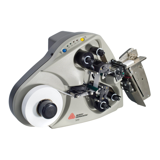
In all other countries, please contact your local AVERY DENNISON supplier. • 2.4 Printer Description Shown below are the important parts of the AVERY DENNISON SNAP 500 Printer. Please take a moment to familiarize yourself with the printer. Control Panel... - Page 15 All manuals and user guides at all-guides.com User’s Manual—SNAP™ 500 Printer The Tape Arbor holds the tape supply roll. By rotating the outer knob • clockwise or counterclockwise, you can adjust the Tape Arbor to accommodate tapes ranging from ½ inch - 2 ¼ inches (12.7 mm - 57.2 mm) wide.
-
Page 16: Setting Up The Printer
All manuals and user guides at all-guides.com User’s Manual—SNAP™ 500 Printer 2.5 Setting Up the Printer 2.5.1 Attaching the Stacker Label Stop Stacker Sensor Switch Rotary Knife Platform Shafts Figure 4. Rotary Knife and Stacker with Bottom Tipped Out The stacker and knife are two separate assemblies that can be installed and/or replaced easily and quickly. -
Page 17: Checking The Main Fuse Configuration
(Line voltage of 90-132VAC @ 50-60Hz, single phase or 180-265VAC @ 50-60Hz, single phase). The main fuse(s) on the AVERY DENNISON SNAP 500 printer are located inside the AC power entry receptacle on the backside of the printer (see Figure 5). The AC power entry has a fuse drawer that holds the fuse(s) and selects the appropriate line voltage. -
Page 18: Installing The Power Cord
2. Plug the power cord into the AC power entry receptacle. 2.5.4 Installing the PC Interface Cable If you will be using your AVERY DENNISON SNAP 500 printer with a personal computer, one of the following computer interface cables is required: Null-modem serial cable with Part number 581139 connector •... - Page 19 All manuals and user guides at all-guides.com User’s Manual—SNAP™ 500 Printer Figure 6. Rear View of the Printer...
-
Page 20: Installing Pcmate Platinum Software
The PCMate Platinum software is a Windows ® application used to create formats for the AVERY DENNISON SNAP 500 printer as well as all other AVERY DENNISON control printers. The printer is also capable of operating directly from a mainframe when using the RS232 interface and AVERY DENNISON's command language (PCL). -
Page 21: Printing The Test Labels
All manuals and user guides at all-guides.com User’s Manual—SNAP™ 500 Printer 1. Press and hold the Voice button until the printer says “Press Start for Test Patterns.” 2. Press the Start button. The printer will say “Press Start for Test Pattern 1.” If you want to print test pattern 1, press the Start Button, then go to step 3. -
Page 22: Operation
User’s Manual—SNAP™ 500 Printer 3.0 Operation 3.1 Loading Supplies Your AVERY DENNISON SNAP 500 printer is designed with both upper and lower ink supply stations. The ink arbors have a spring-loaded latch, which self-centers the roll of ink to ensure smooth tracking through the machine. If you are using supplies based on the metric system, ensure that the latch on the arbor is gray. - Page 23 All manuals and user guides at all-guides.com User’s Manual—SNAP™ 500 Printer Upper Ink Rewind Arbor Upper Print Station Latch Latch Figure 7. Upper Ink Supply and Print Stations - Unloaded NOTE: The ink system is designed to rewind one roll of ink at a time.
- Page 24 All manuals and user guides at all-guides.com User’s Manual—SNAP™ 500 Printer Rewind Core Upper Rewind Arbor Upper Ink Supply Roll Upper Print Station Print Head Lower Print Station Figure 8. Upper and Lower Ink Supply and Print Stations - Loaded 4.
-
Page 25: Installing Ink To The Bottom Ink Supply Station
Before loading a roll of tape, you will need to be familiar with the following parts of the AVERY DENNISON SNAP 500 printer (Refer to Figures 9 and 10). The Tape Arbor is designed to clamp the core of the tape supply rolls to hold them in place during printing operations. - Page 26 All manuals and user guides at all-guides.com User’s Manual—SNAP™ 500 Printer 1. Remove the transparent tape holding the end of the supply tape to the outer part of the roll. To avoid damaging the rollers or print heads, use scissors to cut off any portion of the supply tape that has adhesive on it.
-
Page 27: Butt Splice
CAUTION: To prevent damage to the print head, do not use butt splices. The AVERY DENNISON SNAP 500 printer is designed to allow for fast, frequent changing and loading of tape and supplies. On this model it is quicker to re- thread the tape than to use a butt splice. -
Page 28: Printing Labels
3.3 Printing Labels 3.3.1 The Control Panel The Control Panel on your AVERY DENNISON SNAP 500 printer is located at the top of the machine. Figure 11 shows the control buttons and lights displayed on the printer. The buttons allow you to control the printer, and the lights indicate the status of the printer. -
Page 29: Printing
NOTE: If the error condition no longer exists, the printer will start. It is not necessary to press the Start button twice as is required with previous AVERY DENNISON printer models. If the error continues to recur, contact your local AVERY DENNISON representative. -
Page 30: End Of Day
There a three options for detecting the sense mark: A top reflective sensor is standard on all AVERY DENNISON SNAP 500 • printers. This sensor will detect a black sense mark on the top surface of a white tape, and is mounted in the top right-hand post that holds the web guide. -
Page 31: Selecting The Sensor
All manuals and user guides at all-guides.com User’s Manual—SNAP™ 500 Printer centered on the tape. Refer to Appendix 7 for instructions on teaching the sensor. 3.3.6.1 Selecting the Sensor The top and bottom reflective sensors can be selected in one of two ways. First, the sensor type can be selected as part of the format (see the PCMate Platinum manual or the PCL manual for details). -
Page 32: Running Test Labels
Option Menu System. 3.4.1 Running Test Labels Your AVERY DENNISON SNAP 500 printer offers you two Test Patterns to run before you proceed to production. Test Pattern 1, consisting of a solid line down the middle on the front and back of the label and a solid line across the web that is exactly 1”... - Page 33 All manuals and user guides at all-guides.com User’s Manual—SNAP™ 500 Printer When you have determined which Test Pattern you wish to operate, use the appropriate procedure. NOTE: The printer is set up to print the selected label test format in a very large quantity. You must manually start and stop the printing to make any necessary adjustments and to end the test run.
- Page 34 All manuals and user guides at all-guides.com User’s Manual—SNAP™ 500 Printer Figure 12a. Running Test Patterns Test Pattern 2 1. Press and hold the Voice button for about two seconds. The voice message will state, “Press Start for Test Pattern.” 1.
-
Page 35: Using Voice Demos
User’s Manual—SNAP™ 500 Printer 3.4.2 Using Voice Demos To help you become more familiar with your AVERY DENNISON SNAP 500 printer, the machine is equipped with two voice demos. Demo 1 provides a basic introduction to the printer. Demo 2, consisting of 21 separate voice messages, reviews the basic features of the printer one-by-one. -
Page 36: Setting / Adjusting Voice Button Volume
Figure 12b. Running Voice Demos 3.4.3 Setting / Adjusting Voice Button Volume The volume level of the voice messages on your AVERY DENNISON SNAP 500 printer is set at Level 3 at the factory. If you want to adjust the voice button’s volume setting on your printer, follow the steps listed below. - Page 37 All manuals and user guides at all-guides.com User’s Manual—SNAP™ 500 Printer 6. Press the Voice button. The voice message says, “Press Start for Volume Level 4.” 7. Press the Voice button. The voice message says, “Press Start for Volume Level 5.” 8.
-
Page 38: Making Adjustments
4.0 Making Adjustments 4.1 Print Head Adjustments The two print stations on the AVERY DENNISON SNAP 500 printer are stationary. The print rollers swing open for loading tape and ink and are closed when the machine is printing. The rollers are held in the print position with a latch on both the inside and outside end of the rollers. -
Page 39: Adjusting Density (Darkness)
In fact, it may actually begin to get lighter. 4.2 Adjusting the Stacker The stacker on your AVERY DENNISON SNAP 500 printer is adjustable in four ways: the position of the stacker on the mounting pins, the height of the stack, the angle at which labels are accumulated in the stack, and the angle of the platform. -
Page 40: Stacker Position
All manuals and user guides at all-guides.com User’s Manual—SNAP™ 500 Printer 4.2.1 Stacker Position The stacker slides in and out on the mounting pins. This allows for proper positioning of the stacker for the width of the label you are printing. The stacker should be set so that the back wall of the stacker is just behind the back end of the label where it comes out of the nip rollers. -
Page 41: Platform
All manuals and user guides at all-guides.com User’s Manual—SNAP™ 500 Printer Label Stop Stacker Sensor Switch Platform Shafts Adjustment Figure 14. Stacker Angle – Almost Vertical 4.2.4 Platform The platform angle can be adjusted in two different locations to alter the angle at which labels are stacked and stopped. -
Page 42: Print And Cut Adjustments
All manuals and user guides at all-guides.com User’s Manual—SNAP™ 500 Printer Label Stop Platform Adjustment Pin Figure 15. Stacker Platform Angle Adjustment 4.3 Print and Cut Adjustments The print and cut adjustments allow you to compensate for mechanical tolerances in the printer so that the print is positioned correctly and the cut occurs at the right place. -
Page 43: Print Adjust
Platinum manual for details. 4.4 Printer Features The AVERY DENNISON SNAP 500 printer has many features that can be controlled by the operator. Each of these features can be selected from either the Virtual Control Panel (see section 8.0) or the Remote Control / Display Module (see section 7.0). -
Page 44: Setting The Date And Time
4.4.2 Setting the Date and Time The AVERY DENNISON SNAP 500 printer has a built-in clock and calendar. You may change the date and time as follows: In the Virtual Control Panel, access the Options Tab. The current printer date and time is shown. -
Page 45: Selecting The Flagging Mode
Format – use the print speed specified in the format. If the print speed • does not exist in the AVERY DENNISON SNAP 500 printer, it will use the closest print speed that is not greater. For example, if the format was designed for a 676 printer and calls for 5 ips, the AVERY DENNISON SNAP 500 printer will use 4.5 ips. -
Page 46: Setting The Default Transfer Type
Enter key to accept it. 4.4.8 Viewing the Life Counts The AVERY DENNISON SNAP 500 printer maintains a count of the total number of labels printed, and the total number of inches of material. Also, there is a resettable label counter. -
Page 47: Maintenance
Wear anti-static gloves at all times when handling print heads to prevent oils on your hands from contaminating the print head. The AVERY DENNISON SNAP 500 printer spare parts kit contains an anti-static wrist strap and gloves. -
Page 48: Cleaning Procedures
CAUTION: AVERY DENNISON recommends Master Cleaning Kit #921341K for use in cleaning print heads. 1. Before cleaning any part of your AVERY DENNISON SNAP 500 printer, turn off the power to the printer. 2. To avoid damaging the print head, wear the anti-static wrist strap (which must be in contact with the skin and be tight). -
Page 49: Print Head Replacement
All manuals and user guides at all-guides.com User’s Manual—SNAP™ 500 Printer 5.2 Print Head Replacement When you see voids in the printing, and print quality does not improve, even after cleaning the heads, it is time to replace the print heads. Follow the procedures listed below. - Page 50 All manuals and user guides at all-guides.com User’s Manual—SNAP™ 500 Printer Reach underneath and remove the print head assembly from the print station. Figure 17a. Unplugging Print Head Cable Figure 17b. Two Tabs on Print Station - Depressed Figure 17c. Print Head Assembly – Removed Figure 17d. Inserting Print Head Assembly Figure 17e.
-
Page 51: Lubrication
5.4 Rotary Knife Assembly The rotary knife assembly for the AVERY DENNISON SNAP 500 printer sets into a groove in the mounting bracket and is locked in place with a single screw. It has been designed to deliver an average of two million cuts if used with woven tapes and four million cuts when used with coated tapes, provided no foreign objects are inserted into the assembly that could damage the knife blades. -
Page 52: Removing And Replacing The Knife Assembly
All manuals and user guides at all-guides.com User’s Manual—SNAP™ 500 Printer 5.4.1 Removing and Replacing the Knife Assembly WARNING: When adjusting, removing, or replacing the knife assembly, you must turn off the power to the printer to avoid personal injury. 1. -
Page 53: Adjust The Knife Home Position
All manuals and user guides at all-guides.com User’s Manual—SNAP™ 500 Printer 8. Properly dispose of the used knife assembly. 9. To insert the new knife assembly, slide it down vertically into the space between the Auxiliary Feed and the Nip Rollers. 10. -
Page 54: Service Adjustments
(see Sect. 5.4.2, Knife Home Position Adjustment). 6.4 Knife Shear Adjustment The Knife Assembly in your AVERY DENNISON SNAP 500 printer has no field replacement components, and basically requires no maintenance or adjustments. The only adjustment that can be made to the knife in the field is for shear. - Page 55 All manuals and user guides at all-guides.com User’s Manual—SNAP™ 500 Printer 1. Turn off the power to the printer. 2. Remove the knife assembly from the printer as described in Section 4.4.1. Refer to Figures 18a and 18b. 3. Loosen the outer pivot screw by making one complete turn (see Fig. 19a). 4.
-
Page 56: Remote Control / Display Module
User’s Manual—SNAP™ 500 Printer 7.0 Remote Control / Display Module If your AVERY DENNISON SNAP 500 printer is connected to a mainframe rather than a personal computer, you may use the Remote Control / Display module (see Figure 20) for various functions. This module serves as a standalone controller and a printer status display so you can adjust the parameters of your print runs and observe the current status of the printer. -
Page 57: Controlling The Printer
Start—If batches are present, this button initiates printing. • Feed—This button has no function in the AVERY DENNISON SNAP 500 • printer. Test – This button has no function in the AVERY DENNISON SNAP 500 • printer. Stop—Stops the printer. •... - Page 58 All manuals and user guides at all-guides.com User’s Manual—SNAP™ 500 Printer correct, then press either the MODE key (to go on to the next menu entry) or EXIT to exit the menu system.
-
Page 59: Virtual Control Panel
PCMate Platinum has the capability of controlling the AVERY DENNISON SNAP 500 printer and making adjustments right on the PC. When a AVERY DENNISON SNAP 500 printer is connected to PCMate Platinum (see the PCMate Platinum manual for details about printer connections), and the Print Module is active, a Virtual Control Panel is displayed at the bottom of the PCMate Platinum window (see figure 21). -
Page 60: Viewing And Changing Printer Settings
All manuals and user guides at all-guides.com User’s Manual—SNAP™ 500 Printer You can clear the current batch or all batches using the Batch Control buttons on the right side of the window. 8.1 Viewing and Changing Printer Settings The printers’ settings can be viewed and changed using the Virtual Control Panel. -
Page 61: Upgrading The Printer Software
9.0 Upgrading the Printer Software 9.1 Introduction The AVERY DENNISON SNAP 500 printer software can be updated electronically. Software upgrades are distributed as a single file called the upgrade or UPG file. PCMate Platinum will take the UPG file and automatically upgrade the printer. - Page 62 All manuals and user guides at all-guides.com User’s Manual—SNAP™ 500 Printer Click on the Yes button to start the upgrade. Clicking on the No button will take you into PCMate Platinum. Each time you start up PCMate Platinum, this screen will appear until you either perform the upgrade or remove it (see below).
- Page 63 All manuals and user guides at all-guides.com User’s Manual—SNAP™ 500 Printer The upgrade process can take quite a while. If the process is interrupted, the printer will attempt to revert to the last revision. If it fails, it will revert to a safe version. If this occurs, it will be necessary to redo the upgrade.
- Page 64 All manuals and user guides at all-guides.com User’s Manual—SNAP™ 500 Printer The printer will reboot and say, “Upgrade in progress. Please wait.” After a few minutes, the printer will reboot again. It will then say “Programming MCB. Please wait” At this time, the lights on the printer control panel will all come on. After a few minutes, the printer will reboot again.
-
Page 65: Electrical Troubleshooting
All manuals and user guides at all-guides.com User’s Manual—SNAP™ 500 Printer 10.0 Electrical Troubleshooting 10.1 Power Up / Sign On / Communications Problem Probable Cause Corrective Action LEDs do not light. 1) Incorrect supply voltage. 1) Confirm that the AC entry is configured for the line voltage intended to be applied to the machine. - Page 66 1) Reconfigure PCMate for AVERY PCMate. DENNISON PCL printer as per your PCMate manual. 6) Faulty Mother Board 1) Replace the Mother Board. IF THE RECOMMENDED CORRECTIVE ACTIONS DO NOT RESOLVE THE PROBLEM (S), CONTACT YOUR LOCAL AVERY DENNISON REPRESENTATIVE.
-
Page 67: Tape / Ink Advance
Module, view error message. 3) Tape is bound. 1) Remove and rethread the tape. 4) Ink is bound. 1) Remove and rethread the ink. IF THE RECOMMENDED CORRECTIVE ACTIONS DO NOT RESOLVE THE PROBLEM (S), CONTACT YOUR LOCAL AVERY DENNISON REPRESENTATIVE. -
Page 68: Print
Refer to section 6.2, Tape (Web) Guide Width Adjustments. 3) Tape Arbor is not tight. 1) Check and adjust as needed. Refer to section 3.1 Loading Supplies. IF THE RECOMMENDED CORRECTIVE ACTIONS DO NOT RESOLVE THE PROBLEM (S), CONTACT YOUR LOCAL AVERY DENNISON REPRESENTATIVE. - Page 69 1) Set print head pressure. Refer to section pressure. 4.1.1, Adjusting Print Head Pressure. 5) Worn printer roller. 1) Contact your local AVERY DENNISON representative. IF THE RECOMMENDED CORRECTIVE ACTIONS DO NOT RESOLVE THE PROBLEM (S), CONTACT YOUR LOCAL AVERY DENNISON REPRESENTATIVE.
-
Page 70: Cut / Stack
Adjustment. Knife will not cut. 1) Knife blades are dull. 1) Refer to section 5.4.1, Removing and Replacing the Knife assembly. IF THE RECOMMENDED CORRECTIVE ACTIONS DO NOT RESOLVE THE PROBLEM (S), CONTACT YOUR LOCAL AVERY DENNISON REPRESENTATIVE. -
Page 71: Printer Errors
All manuals and user guides at all-guides.com User’s Manual—SNAP™ 500 Printer 10.5 Printer Errors Printer errors are indicated by either the Supply or Error light being on. When the Supply light is on, the printer supplies (tape or ink) require attention. Generally, this means the tape or one of the ink rolls is empty, or the stacker is full. - Page 72 MCB BAD STACK ERROR continues to occur, report the error and the MCB KNF FLIT TBL TOO circumstances that cause it to AVERY DENNISON Service. These errors are caused by errors in the MCB KNIFE STATE TOO software and are not caused by hardware failures.
- Page 73 All manuals and user guides at all-guides.com User’s Manual—SNAP™ 500 Printer Voice Message Prompt Description The lower (upper) INK OUT BOTTOM (TOP) This error indicates that the ink on the specified print print station ink roll is station is either missing or broken, or the supply roll empty is empty.
- Page 74 MCB with the power off, then replacing it. This will also reset all the printer settings (print and cut adjust, baud rate, cutter enable, etc.) to their default values. IF THE RECOMMENDED CORRECTIVE ACTIONS DO NOT RESOLVE THE PROBLEM (S), CONTACT YOUR LOCAL AVERY DENNISON REPRESENTATIVE.
-
Page 75: Mechanical Troubleshooting
1) Be sure the nip roller is free to rotate and moves easily in the bearing slots. Check for a loose drive gear. IF THE RECOMMENDED CORRECTIVE ACTIONS DO NOT RESOLVE THE PROBLEM (S), CONTACT YOUR LOCAL AVERY DENNISON REPRESENTATIVE. -
Page 76: User's Manual-Snap™ 500 Printer
Tape is popping in front 1) Knife blades are dull. 1) Refer to section 5.4.1, Removing and of the knife. Replacing the Knife Assembly. IF THE RECOMMENDED CORRECTIVE ACTIONS DO NOT RESOLVE THE PROBLEM (S), CONTACT YOUR LOCAL AVERY DENNISON REPRESENTATIVE. -
Page 77: Appendices
Appendices 1. Fuse Configuration The main fuse(s) on the AVERY DENNISON SNAP 500 are located inside the AC power entry receptacle. The entry has a fuse drawer that holds the fuse(s) and selects the appropriate line voltage. If the number in the window DOES NOT match the AC line voltage intended to be supplied to the printer, DO NOT plug the power cord in. -
Page 78: Reconfiguring The Internal Power Supply
All manuals and user guides at all-guides.com User’s Manual—SNAP™ 500 Printer 1.2 Reconfiguring the Internal Power Supply Check the fuse label on the back cover of the printer. If the fuse label has the warning shown below, you must perform the following procedure to reconfigure the internal power supply to 115V or 230V. - Page 79 All manuals and user guides at all-guides.com User’s Manual—SNAP™ 500 Printer Power Supply 4) The voltage selector switch is found on the side of the power supply facing the MCB. See the picture below. To access the switch, it may be necessary to remove the mounting screws and carefully move the power supply away from the MCB.
-
Page 80: Ink And Tape Transfer Types
All manuals and user guides at all-guides.com User’s Manual—SNAP™ 500 Printer 2. Ink and Tape Transfer Types Transfer Type values associated with the XT commands. Value Transfer Type Heat Seal & SD-1111 Ink Fabric 2800 & TT-1111 Ink Fabric 2800 & HR-3111 Ink Fabric 2800 &... - Page 81 All manuals and user guides at all-guides.com User’s Manual—SNAP™ 500 Printer Value Transfer Type 601SST Fabric & CT-1111 Ink 591SST/601SST Fabrics & CT-1115 Ink 591SST/601SST Fabrics & CT-1117 Ink 591SST Fabric & CT-1112 Ink 601SST Fabric & CT-1112 Ink 4900NWT / 4900HSA & HS1111 1800FRA &...
-
Page 82: Printer Specifications
All manuals and user guides at all-guides.com User’s Manual—SNAP™ 500 Printer 3. Printer Specifications Print Narrow web thermal transfer two sided printer method: Speeds - 3 IPS (76.2mm/second), 4.5 IPS (114.3mm/second), 6 IPS (152.4mm/second), 7 IPS (177.8mm/second) Label Size Min: 1/2" (12.7mm) web x 1 .062" (26.9mm) feed at 3 IPS and 4.5 IPS (standard stacker) Min: 1/2"... - Page 83 - Missed sense mark detection and correction Ink Ribbon AVERY DENNISON standard thermal colors and widths AVERY DENNISON white plastic core: Maximum Ink I.D. 3.5” Ink widths: With Metric Adapter - 25mm, 30mm, 35mm 40mm, 45mm, 50mm or 60mm metric widths only.
-
Page 84: Instructions For Factory / Field Installation Of Back Reflective Sensor 580010
All manuals and user guides at all-guides.com User’s Manual—SNAP™ 500 Printer 4. Instructions for Factory / Field Installation of Back Reflective Sensor 580010 Installation Procedure 1. Disconnect Power to Printer. 2. Disconnect Stacker Cable & Remote Control Panel (if so equipped). 3. - Page 85 All manuals and user guides at all-guides.com User’s Manual—SNAP™ 500 Printer 7. With a Dremel Tool, open these holes to create a rectangle large enough to accept the ½ X ¾ flat end of the Sensor Mount Block. Be sure Rectangle is located to accept the mounting 8-32 screw through the Upright Frame.
-
Page 86: Sensor Installation
All manuals and user guides at all-guides.com User’s Manual—SNAP™ 500 Printer Sensor Installation 1. Assemble the Sensor / Harness Assembly into the slot in the Mounting Block, flush with the top and with the Harness in the slot to the flat end of the Block. -
Page 87: Final Assembly
All manuals and user guides at all-guides.com User’s Manual—SNAP™ 500 Printer Final Assembly 1. Replace Web Guide Assembly and Reconnect Electrically. Secure with saved screws (10-32). 2. Reassemble Rear Cover with Saved Screws (8-32). 3. Reconnect stacker cable and remote instrument panel 4. -
Page 88: Installation Procedure, Front Of Printer
All manuals and user guides at all-guides.com User’s Manual—SNAP™ 500 Printer 5. Instructions for Factory / Field Installation of Top Sensor Assemblies 580009 & 580011 The above sensors are alike in mechanical configuration. 580009 is a color contrast sensor & 580011 is a contrast sensor only. Installation Procedure, Front of Printer 1. - Page 89 All manuals and user guides at all-guides.com User’s Manual—SNAP™ 500 Printer 5. Locate a small detent point on the Front Cover directly above the shaft as described in step 4. Using this detent as a center, drill a small 3/16- diameter guide hole through the Front Cover.
- Page 90 All manuals and user guides at all-guides.com User’s Manual—SNAP™ 500 Printer DETENT CREATE EITHER 1/2 SQUARE OR 5/8 DIA. HOLE Factory Installation will perform this step prior NOTE: to assembly. 6. Assemble the “Y” shaped fiber optic pickup lead into the “L” bracket, rotate 90°...
- Page 91 All manuals and user guides at all-guides.com User’s Manual—SNAP™ 500 Printer 7. Slide the square portion of the “L” bracket through the newly created hole in the Front Cover and the pickup tube into the slot in the Web Guide Shaft between the guides. SLOT IN FRONT COVER FIBER OPTIC CABLE 8.
-
Page 92: Installation Procedure, Rear Assembly
All manuals and user guides at all-guides.com User’s Manual—SNAP™ 500 Printer Installation Procedure, Rear Assembly 1. Assemble Sensor Mounting Bracket to Sensor body with (2) 8-32 x ¼ Button Head Screws. MCB POWER CABLE CONNECTOR SENSOR MOUNT BRACKET 4X 8-32 X 1/4 BUTTON HEAD SCREW SENSOR 2. - Page 93 All manuals and user guides at all-guides.com User’s Manual—SNAP™ 500 Printer 5. Assemble Sensor Power Cable to Sensor and plug into MCB Connector labeled “Option Top Color / Contrast”.
-
Page 94: Final Assembly
All manuals and user guides at all-guides.com User’s Manual—SNAP™ 500 Printer Final Assembly 1. Using the supplied Template, scribe a cutout line on the Rear Cover. SCRIBE TEMPLATE SCRIBE AND REMOVE THIS MATERIAL 2. Remove the material within this scribed line. Drill corners and use Dremel tool or small saw. -
Page 95: Contrast Sensor Assembly Drawing
All manuals and user guides at all-guides.com User’s Manual—SNAP™ 500 Printer Contrast Sensor Assembly Drawing Item Part # Description 584031 Pin, Extension 584032 Slide, Contrast sensor 196028 Knob, Adjust 584030 Shaft, Contrast sensor mount 581315 Light guide, Fiber optic 581124 Cable, Contrast sensor 581316 Bracket, Contrast sensor mount... -
Page 96: Instructions For Factory / Field Installation Of High Speed Verifier Assembly 580015
All manuals and user guides at all-guides.com User’s Manual—SNAP™ 500 Printer 6. Instructions for Factory / Field Installation of High Speed Verifier Assembly 580015 Installation Procedure - Mechanical 1) Disconnect Power to Printer. 2) Disconnect Stacker Cable & Remote Control Panel (if so equipped). 3) Remove the Rear Cover (save screws). - Page 97 All manuals and user guides at all-guides.com User’s Manual—SNAP™ 500 Printer 6) Install Verifier Mount Plate using (2) 6-32 x 3/8 Cap Screws & attach the Verifier to the Plate with the remaining (2) 6-32 x 3/8 Cap Screws. VERIFIER MOUNT PLATE 6-32 X 3/8 CAP SCREWS (4) VERIFIER...
-
Page 98: Installation Procedure - Electrical
All manuals and user guides at all-guides.com User’s Manual—SNAP™ 500 Printer Installation Procedure – Electrical 1) Facing the back of the Printer, remove the pre-punched material from the horizontal slot (shown below) in the Mother Board Mounting Plate. KNOCK OUT PRE-PUNCHED SLOT 2) Assemble Internal Verifier Cable into slot and secure with hardware supplied on 581129. -
Page 99: Installation - Rear Cover
All manuals and user guides at all-guides.com User’s Manual—SNAP™ 500 Printer Installation – Rear Cover 1) Insert the Template supplied into the Cover hole above and closest to the above Verifier / Bracket Assembly. Bending the Template slightly to match the Cover contour will assure a more accurate location. - Page 100 All manuals and user guides at all-guides.com User’s Manual—SNAP™ 500 Printer Item Part # Description 581302 Bracket, Verifier frame mount 581307 Bracket, Verifier mount 581309 Plate, Verifier mount 990084 10-32 x 1 Cap screw 551144 Verifier, 8" 990016 6-32 x 3/8 Cap screw 581144 Harness, External verifier (not shown) 990122...
-
Page 101: Programming The Contrast Sensors
User’s Manual—SNAP™ 500 Printer 7. Programming the Contrast Sensors There are two optional contrast sensors available for the SNAP 500 printer. 580011 is the standard contrast sensor. It works well in most situations where there is significant contrast between the material background and the sense mark. In situations were there is less contrast between the material and the sense mark, or the material and sense mark are of similar colors, 580009 may be required. -
Page 102: Programming The 580009 Contrast Sensor
All manuals and user guides at all-guides.com User’s Manual—SNAP™ 500 Printer index finger, while applying back tension to the supply roll with the left thumb. This ensures that the stock is in the same position that it will be when the printer is running. Release the TEACH button. - Page 103 All manuals and user guides at all-guides.com User’s Manual—SNAP™ 500 Printer Make sure that the stock is tight against the web guide. The best way to do this is to press the TEACH button with the left index finger, while applying back tension to the supply roll with the left thumb.
-
Page 104: Warranty Information
− Consumable elements are not covered. Consumable elements are those that show normal wear from typical equipment usage including, without limitation, printheads, knives, rollers in contact with the web, and sonic units. Avery Dennison reserves the right to determine which elements are defined as “consumable.”... - Page 105 Americas (United States, Canada, Mexico, Central America, Caribbean Region, and South America excluding Brazil). − Outside the US, the local Avery Dennison office is responsible for equipment and parts warranty. Customers must ensure coverage during machine purchase. − Equipment purchased and exported to regions outside local Avery Dennison office coverage are not covered by warranty.
- Page 106 All manuals and user guides at all-guides.com...
-
Page 107: Option Menu System Flowchart
All manuals and user guides at all-guides.com User’s Manual—SNAP™ 500 Printer 9. Option Menu System Flowchart... - Page 108 All manuals and user guides at all-guides.com User’s Manual—SNAP™ 500 Printer PRESS START BUTTON TO ACCEPT THE CURRENT OPTION PRESS AND HOLD VOICE BUTTON UNTIL OPTION PRESS VOICE BUTTON TO GO TO THE NEXT OPTION MENU BEGINS NOTE: PRESS AND HOLD THE VOICE BUTTON AT ANY TIME TO EXIT THE VOICE MENU SYSTEM. PRESS START FOR PRESS START FOR TEST PRESS START FOR...
-
Page 109: Electrical Assembly Drawings
All manuals and user guides at all-guides.com User’s Manual—SNAP™ 500 Printer Electrical Assembly Drawings... -
Page 110: Electrical System Schematic
All manuals and user guides at all-guides.com User’s Manual—SNAP™ 500 Printer Electrical System Schematic DIODE 990998 HARNESSED 24V POWER SUPPLY 581119F FACTORY 581116 581119K FIELD 581188 RETURN AC ENTRY 115V 341111 581113 230V 581112 MINI FP 990890 LINE LINE CORD PART OF GROUND 581118 ATX... -
Page 111: Harness Connections
All manuals and user guides at all-guides.com User’s Manual—SNAP™ 500 Printer Harness Connections FEED FEED MOTOR - J13 24V - J21 KNIFE MOTOR - J15 KNIFE KNIFE HOME - J27 SPEAKER SPEAKER - J38 UNWIND MEDIA UNWIND - J17 STACKER S2 PRINT HEAD - J32 STACKER - J34 S2 INK UNWIND - J19... - Page 112 All manuals and user guides at all-guides.com...
-
Page 113: Mechanical Assembly Drawings
All manuals and user guides at all-guides.com User’s Manual—SNAP™ 500 Printer Mechanical Assembly Drawings... -
Page 114: Unwind Assembly Drawing
All manuals and user guides at all-guides.com User’s Manual—SNAP™ 500 Printer Unwind Assembly Drawing... -
Page 115: Unwind Parts List
All manuals and user guides at all-guides.com User’s Manual—SNAP™ 500 Printer Unwind Parts List Item Part # Description Item Part # Description 581201 Frame, Upright (reference only) 126468 Motor, Ribbon 118052 Holder, Bearing 989971 5/16 - 18 x 3/8 Set screw 117903 Bearing, Platen 583009 Drag plug, Unwind 117955 Gear, Ribbon, 54T - 15T... -
Page 116: Web Guide Assembly Drawing
All manuals and user guides at all-guides.com User’s Manual—SNAP™ 500 Printer Web Guide Assembly Drawing... -
Page 117: Web Guide Parts List
All manuals and user guides at all-guides.com User’s Manual—SNAP™ 500 Printer Web Guide Parts List Item Part # Description 584006 Bracket, Web guide 584009 Shaft, Web guide 584021 Bracket, Micro adjust 118826 Guide, Wear 991447 Spring, Compression 584024 Shaft, Web present sensor 991374 1/4-20 x 1/2 Phillips pan head screw 991373 8-32 x 1/4 Phillips pan head screw 584035 Spacer, Web guide... -
Page 118: Printhead Assembly Drawing
All manuals and user guides at all-guides.com User’s Manual—SNAP™ 500 Printer Printhead Assembly Drawing... -
Page 119: Printhead Parts List
All manuals and user guides at all-guides.com User’s Manual—SNAP™ 500 Printer Printhead Parts List Item Part # Description 585008 Latch, Head - Right 117951 Button, Pressure 585006 Shaft, Head lock 585005 Screw, Special head lock 585007 Latch, Head - Left 585022 Mount, Print head 117950... -
Page 120: Ink Unwind / Rewind Assembly Drawing
All manuals and user guides at all-guides.com User’s Manual—SNAP™ 500 Printer Ink Unwind / Rewind Assembly Drawing... -
Page 121: Ink Unwind / Rewind Parts List
All manuals and user guides at all-guides.com User’s Manual—SNAP™ 500 Printer Ink Unwind / Rewind Parts List Item Part # Description Item Part # Description 581201 Frame, Upright 991370 Torsion spring 118052 Holder, Bearing 991367 Snap ring, 9/64 e-ring 117903 Bearing, Platen 990327 Snap ring, 5/16 e-ring 586007 Shaft, Ink arbor 117954 Gear, Ribbon, 75T... -
Page 122: Upright Frame Assembly Drawing
All manuals and user guides at all-guides.com User’s Manual—SNAP™ 500 Printer Upright Frame Assembly Drawing... -
Page 123: Upright Frame Parts List
All manuals and user guides at all-guides.com User’s Manual—SNAP™ 500 Printer Upright Frame Parts List Item Part # Description 581201K_SH 2 Frame, Upright 581201K_SH 6 Bracket, Support, Rear cover 581201K_SH 7 Frame, Mother board tray 991379 10-32 x 3/8 Phillips pan head screw 991372 6-32 x 1/4 Phillips pan head screw 581204... -
Page 124: Covers Assembly Drawing
All manuals and user guides at all-guides.com User’s Manual—SNAP™ 500 Printer Covers Assembly Drawing... -
Page 125: Covers Parts List
All manuals and user guides at all-guides.com User’s Manual—SNAP™ 500 Printer Covers Parts List Item Part # Description 581201 Frame, Upright 581205 Cover, Rear 581206 Cover, Front 586010 Static Brush 991376 10-30 x ½ Phillips Pan Head Screw 991508 8-32 x ½ Flanged Button Hd. Screw 10... -
Page 126: Feed - Drive Train Assembly Drawing
All manuals and user guides at all-guides.com User’s Manual—SNAP™ 500 Printer Feed – Drive Train Assembly Drawing... -
Page 127: Feed - Drive Train Parts List
#8 SAE WASHER 585012 SHAFT, SWING BLOCK 990068 LOCK WASHER, #8 990486 SNAP RING, 3/8 E-RING 584075 COVER, FEED GUARD, SNAP 500 584012 ROLLER, AUX DRIVE 991636 8-32 X 3/8 PHILLIPS PAN HEAD SCREW 584013 ROLLER, MOLDED, IDLER 594041 SHAFT, AUX. DRIVE SUPPORT... -
Page 128: Knife - Drive - Nip Roller Assembly Drawing
All manuals and user guides at all-guides.com User’s Manual—SNAP™ 500 Printer Knife – Drive – Nip Roller Assembly Drawing... -
Page 129: Knife - Drive - Nip Roller Parts List
All manuals and user guides at all-guides.com User’s Manual—SNAP™ 500 Printer Knife – Drive – Nip Roller Parts List Item Part # Description Item Part # Description 587090-1 Assembly, Knife 999165 Bushing, 3/16 x 1/4 x 1/4 581201 Frame, Upright 990325 Snap ring, 3/16 e-ring 584011 Frame, Knife / Drive... -
Page 130: Rewind Assembly Drawing (Option)
All manuals and user guides at all-guides.com User’s Manual—SNAP™ 500 Printer Rewind Assembly Drawing (Option) -
Page 131: Rewind Parts List (Option)
All manuals and user guides at all-guides.com User’s Manual—SNAP™ 500 Printer Rewind Parts List (Option) Item Part # Description Item Part # Description 111201 Cover 112033 Shaft, 6x6 Rewind 990090 10-32 x 3/8” Button Head Screws 112035 Key, 1/8 x 1/8 x 3/8” 111029 Base 112034 Decurler Shaft 112037 Support, Shaft Bearing... - Page 132 All manuals and user guides at all-guides.com User’s Manual—SNAP™ 500 Printer...
- Page 133 All manuals and user guides at all-guides.com User’s Manual—SNAP™ 500 Printer AVERY DENNISON Technical Support Product / Services Installation Report (For office use) Customer: Failure Report #: Address: Service Report #: Failure Reported Date: Model #: Contact: Serial #: Phone #: Mfg.
- Page 134 All manuals and user guides at all-guides.com User’s Manual—SNAP™ 500 Printer Revision Record Revision Date Description 12/3/12 Removed CE mark from manual as not required Update FCC ID and moved to page 2 Moved WEEE symbol to page 2 Revision Date Description 5.3 .1...
Need help?
Do you have a question about the SNAP 500 and is the answer not in the manual?
Questions and answers