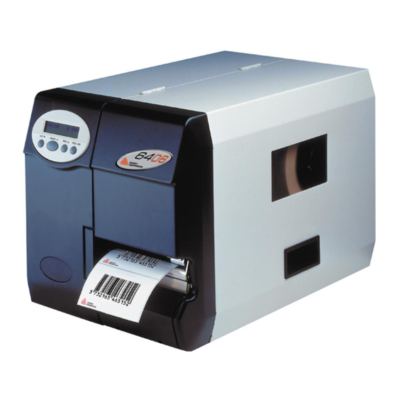
Avery Dennison 64 Series Service Manual

Avery Dennison 64 Series Service Manual

Dispenser
Table of Contents

Advertisement

Quick Links

03/10 Rev. 5.04-04
Service Mechanics
General Notes................................................ 3
Safety Instructions...................................... 3
Special key combinations........................... 4
Serial numbers ........................................... 4
Factory settings .......................................... 5
Service data ............................................... 5
Housing.......................................................... 6
Important instructions ................................. 6
Overview of housing parts.......................... 6
Front hood .................................................. 6
Rear hood .................................................. 7
Left front housing........................................ 8
Right front housing ..................................... 9
Right lower housing.................................... 9
Cutter cover................................................ 9
Plug cover .................................................. 9
Material unwinder......................................... 10
Servicing the unwinder ............................. 10
Tension arm ............................................. 12
Bearing bushes ........................................ 12
Ribbon transport unit.................................... 13
Important notes ........................................ 13
Setting the ribbon zero line ...................... 27
Setting the braking torque ........................ 27
Ribbon core brake .................................... 30
Ribbon guide ............................................ 30
Ribbon transport roller.............................. 31
Ribbon end sensor ................................... 32
SERVICE MANUAL
64-xx - 64-xx Dispenser
Feed unit.......................................................35
Construction of the feed unit .....................35
Feed rollers ...............................................35
Contact roller unit......................................37
Material guide ...........................................38
Material end sensor ..................................39
Punch sensor ............................................40
Printhead ......................................................41
Overview printhead settings......................42
Replacing the printhead ............................43
Printhead adjustment....................................44
Setting the head aperture .........................44
Print head lift mechanic ................................49
Print head sensor......................................49
Print head motor .......................................50
Contact pressure lever..............................50
Connections and electrics ............................51
Important instructions................................51
Power Supply............................................52
Motor / Sensor Cable harness ..................54
Cover switch .............................................58
Overview of the sensors ...............................59
Boards (Gen. 2) ............................................60
CPU board ................................................60
Motor driver board.....................................62
Operating panel ........................................63
Boards (Gen. 3) ............................................64
Operation panel ........................................64
CPU board ................................................65
Motor output stage boards ........................67
I/O board ...................................................69
Centronics board.......................................70
USI board..................................................71
Service Mechanics

Advertisement

Table of Contents
loading

Summary of Contents for Avery Dennison 64 Series

  • Page 1: Table Of Contents

    03/10 Rev. 5.04-04 SERVICE MANUAL Service Mechanics 64-xx – 64-xx Dispenser Service Mechanics General Notes..........3 Feed unit............35 Safety Instructions........3 Construction of the feed unit .....35 Special key combinations......4 Feed rollers ..........35 Serial numbers ........... 4 Contact roller unit........37 Factory settings ..........
  • Page 2 03/10 Rev. 5.04-04 SERVICE MANUAL Service Mechanics 64-xx – 64-xx Dispenser Assembling accessories ......73 Dustfilter for 64-xx with serial number 075580 or higher........81 Antistatic kit ..........73 Index.............83 Remote operator panel......77 Dustfilter for 64-08 up to serial number 075580 .............
  • Page 3: General Notes

    03/10 Rev. 5.04-04 SERVICE MANUAL Service Mechanics 64-xx – 64-xx Dispenser General Notes Safety Instructions WARNING! The printer operates using mains voltage! Touching electrically live parts can cause exposure to hazardous electrical currents and may lead to burns. Only authorised service technicians are permitted to disassemble the housing.
  • Page 4: Special Key Combinations

    03/10 Rev. 5.04-04 SERVICE MANUAL Service Mechanics 64-xx – 64-xx Dispenser Special key combinations Some printer functions are ought to be only accessible to the authorized service technician. Those functions can therefore not be selected easily. To activate them, the printer has to be restarted, while simultaneously a certain key combination is pressed for some seconds.
  • Page 5: Factory Settings

    03/10 Rev. 5.04-04 SERVICE MANUAL Service Mechanics 64-xx – 64-xx Dispenser Factory settings All parameters are preset ex works to values specific to each device type. These factory settings can be restored at all times with the parameter SPECIAL FUNCTION > Factory settings.
  • Page 6: Housing

    03/10 Rev. 5.04-04 SERVICE MANUAL Service Mechanics 64-xx – 64-xx Dispenser Housing Important instructions The housing may only be opened by authorised trained personnel! Before opening the housing, switch off the device and pull out the mains plug! If this is not done, there is a danger of accidents being caused by dangerous contact voltage.
  • Page 7: Rear Hood

    03/10 Rev. 5.04-04 SERVICE MANUAL Service Mechanics 64-xx – 64-xx Dispenser Rear hood Disassembling The rear hood (2) can be removed by unscrewing the 6 Phillips screws (1). Prise off the rear hood somewhat to the side in order to lift the metal tab (3) out of its recess and at the same time remove it with an upward movement.
  • Page 8: Left Front Housing

    03/10 Rev. 5.04-04 SERVICE MANUAL Service Mechanics 64-xx – 64-xx Dispenser Left front housing Disassembling/assembly 1. Unscrew the Phillips screws (1). 2. Carefully remove the front housing (2) to the side. 3. Pull off the flat ribbon cable plug (3) at the rear of the operating panel.
  • Page 9: Right Front Housing

    03/10 Rev. 5.04-04 SERVICE MANUAL Service Mechanics 64-xx – 64-xx Dispenser Right front housing Disassembling/assembly The right front housing (1) is fixed to the front hood with six Phillips screws (2) and can be removed. Tool Phillips screwdriver Right lower housing Disassembling/assembly The right lower housing (3) is fixed to the base pan by two Allan key screws...
  • Page 10: Material Unwinder

    03/10 Rev. 5.04-04 SERVICE MANUAL Service Mechanics 64-xx – 64-xx Dispenser Material unwinder The material unwinder comprises the unwinder (1) and the tension arm (2). The tension arm is for counteracting jolting movements of the material which can be caused by sudden acceleration or braking. The unwinder itself is braked and can be adjusted to different core diameters.
  • Page 11: Adjusting The Unwinders Brake Torque

    03/10 Rev. 5.04-04 SERVICE MANUAL Service Mechanics 64-xx – 64-xx Dispenser Adjusting the unwinders brake torque • Tools Spring balance 5 N (1) (article no. 93665-01 • Reel with wound-up textile ribbon (Ø 76 mm or 3") (2) Fig. 1 Left side: Aid for adjusting the brake torque: Reel with textile ribbon (2) and spring balance (1).
  • Page 12: Tension Arm

    03/10 Rev. 5.04-04 SERVICE MANUAL Service Mechanics 64-xx – 64-xx Dispenser Tension arm Design changes Serial no. Changed item Date 0663910 Simple tension arm spring 06/2006 (type 1) was replaced by spring with rope drive and pulley (type 2). Rectangular self-adhesive stoppers were replaced by cylindrical screw-in stoppers.
  • Page 13: Ribbon Transport Unit

    03/10 Rev. 5.04-04 SERVICE MANUAL Service Mechanics 64-xx – 64-xx Dispenser Ribbon transport unit Important notes Components The ribbon transport unit (part of the print module) consists of: – Ribbon unwinding mandrel (1a) with brake mechanism (1b) – Ribbon rewinding mandrel (2a) with drive (2b) –...
  • Page 14 03/10 Rev. 5.04-04 SERVICE MANUAL Service Mechanics 64-xx – 64-xx Dispenser Lubricating plastic parts All plastic parts pictured below must be greased at the inner diameter (arrow) before assembling it. All other surfaces must be absolutely free of grease.
  • Page 15: Ribbon Unwinding Mandrel (Type 1)

    03/10 Rev. 5.04-04 SERVICE MANUAL Service Mechanics 64-xx – 64-xx Dispenser Ribbon unwinding mandrel (type 1) Tools – 2.5 and 2 mm allen keys – Size 7 and 8 socket wrenches – Plastic hammer – Philips screwdriver, medium size Preparation for dismantling 1.
  • Page 16 03/10 Rev. 5.04-04 SERVICE MANUAL Service Mechanics 64-xx – 64-xx Dispenser Disassembling 1. Turn out the threaded rod. To do this, turn the red hexagon head (on the side of the print head ) in an anti-clockwise direction. Hold the cap (1) while doing this.
  • Page 17: Ribbon Unwinding Mandrel (Type 2)

    03/10 Rev. 5.04-04 SERVICE MANUAL Service Mechanics 64-xx – 64-xx Dispenser 8. Tighten the fastening nut until the threaded rod protrudes about one millimetre out of the nut. 9. Assemble the ribbon photoelectric switch and contact spring. Ribbon unwinding mandrel (type 2) Tools –...
  • Page 18 03/10 Rev. 5.04-04 SERVICE MANUAL Service Mechanics 64-xx – 64-xx Dispenser Disassembly 1. Turn the threaded rod by the hexagonal head out of the cap (1) and pull it out of the ribbon mandrel. 2. Remove cap (1), spacer ring, spring (2) shim rings, timing disc (3) and brake disc (4).
  • Page 19 03/10 Rev. 5.04-04 SERVICE MANUAL Service Mechanics 64-xx – 64-xx Dispenser Assembly To assemble the device, follow the steps in the reverse order. Make sure to do the following: Mount the stop disc (6) with the larger chamfer pointing outwards. Lightly grease the bearing surface of the brake lever (5) before assembly (with universal grease).
  • Page 20: Ribbon Unwinding Mandrel (Type 3)

    03/10 Rev. 5.04-04 SERVICE MANUAL Service Mechanics 64-xx – 64-xx Dispenser Ribbon unwinding mandrel (type 3) Tools – 2.5 and 2 mm allen keys – Size 7 and 8 socket wrenches – Plastic hammer Preparation for disassembling 1. Remove front and rear hood. 2.
  • Page 21 03/10 Rev. 5.04-04 SERVICE MANUAL Service Mechanics 64-xx – 64-xx Dispenser Disassembly Assembly 1. Turn the threaded rod by the hexagonal To assemble the device, follow the steps in the head out of the cap (1) and pull it out of reverse order: the ribbon mandrel.
  • Page 22: Ribbon Rewinding Mandrel (Type 1)

    03/10 Rev. 5.04-04 SERVICE MANUAL Service Mechanics 64-xx – 64-xx Dispenser Ribbon rewinding mandrel (type 1) Tools – 2.5/2 mm allen keys – Size 7/8 socket wrenches – Philips-screwdriver, small size – Plastic hammer Preparation for disassembling 1. Remove front and rear hood. 2.
  • Page 23: Ribbon Rewinding Mandrel (Type 2)

    03/10 Rev. 5.04-04 SERVICE MANUAL Service Mechanics 64-xx – 64-xx Dispenser Assembly To assemble the device, follow the steps in the reverse order. Make sure to do the following: Mount the stop disc with the larger chamfer pointing outwards. Lightly grease the bearing surface of the belt disc (6) before assembly (with universal grease).
  • Page 24 03/10 Rev. 5.04-04 SERVICE MANUAL Service Mechanics 64-xx – 64-xx Dispenser Disassembly Assembly 1. Turn the threaded rod by the hexagonal To assemble the device, follow the steps in the head out of the cap (1) and pull it out of reverse order.
  • Page 25: Ribbon Rewinding Mandrel (Type 3)

    03/10 Rev. 5.04-04 SERVICE MANUAL Service Mechanics 64-xx – 64-xx Dispenser Ribbon rewinding mandrel (type 3) Tools – 2.5/2 mm allen keys – Size 7/8 socket wrenches – Plastic hammer Preparation for disassembling 1. Remove cap (1). 2. Remove front and rear hood. 3.
  • Page 26 03/10 Rev. 5.04-04 SERVICE MANUAL Service Mechanics 64-xx – 64-xx Dispenser Set the distance between cap and ribbon Disassembly mandrel (X) to the value given in the 1. Turn the threaded rod by the hexagonal following table: head out of the cap (1) and pull it out of the ribbon mandrel.
  • Page 27: Setting The Ribbon Zero Line

    03/10 Rev. 5.04-04 SERVICE MANUAL Service Mechanics 64-xx – 64-xx Dispenser Setting the ribbon zero line It is possible to move the ribbon zero line relatively to the label web zero line. To do so, put additional spacing rings (1) on both ribbon mandrels or replace some of the available spacing rings by thicker or thinner ones.
  • Page 28 03/10 Rev. 5.04-04 SERVICE MANUAL Service Mechanics 64-xx – 64-xx Dispenser While pulling at the rewinding mandrel, it is essential to keep the foil feed roller (5) blocked! The pulling force may vary within the indicated tolerances (see table on next page).
  • Page 29 03/10 Rev. 5.04-04 SERVICE MANUAL Service Mechanics 64-xx – 64-xx Dispenser Table below: Brake forces for ribbon unwind and ribbon rewind mandrel. Printer Tractive force rewind Tractive force unwind Label width mandrel mandrel Min. Setting Max. Min. Setting Max. 64-04 105 mm 64-05 140 mm...
  • Page 30: Ribbon Core Brake

    03/10 Rev. 5.04-04 SERVICE MANUAL Service Mechanics 64-xx – 64-xx Dispenser Ribbon core brake The clamping of the paper core on the ribbon unwinding core and the ribbon roll-up core can be adjusted by setting the spring plate. Setting: 1. Unscrewing the Phillips screws (1). 2.
  • Page 31: Ribbon Transport Roller

    03/10 Rev. 5.04-04 SERVICE MANUAL Service Mechanics 64-xx – 64-xx Dispenser Ribbon transport roller The ribbon transport unit and material transport are usually coupled 1:1. The ribbon is fed over the ribbon transport roller. The ribbon take-up is effected by a slip clutch on the take-up mandrel.
  • Page 32: Ribbon End Sensor

    03/10 Rev. 5.04-04 SERVICE MANUAL Service Mechanics 64-xx – 64-xx Dispenser Ribbon end sensor The ribbon end sensor monitors the movement of an oscillator disc and therefore the presence and movement of the ribbon. A printing process does not take place if ribbon has not been inserted, if the ribbon is torn or if there is no more ribbon available.
  • Page 33: Removing The Complete Print Module

    03/10 Rev. 5.04-04 SERVICE MANUAL Service Mechanics 64-xx – 64-xx Dispenser Removing the complete print module Construction of the print module The following components are mounted on the cast plate (1) of the print module (2): – Feed unit – Material guide –...
  • Page 34 03/10 Rev. 5.04-04 SERVICE MANUAL Service Mechanics 64-xx – 64-xx Dispenser 4. Unscrew and remove the stabiliser (2) in the mechanical part (1 Allan key screw at top and bottom). 5. Detach the earth connection (3) of the print module from the housing. 6.
  • Page 35: Feed Unit

    03/10 Rev. 5.04-04 SERVICE MANUAL Service Mechanics 64-xx – 64-xx Dispenser Feed unit Construction of the feed unit The complete feed unit (1) consists of the following components: – Feed rollers (x2) – Contact roller unit – Print head mounting –...
  • Page 36 03/10 Rev. 5.04-04 SERVICE MANUAL Service Mechanics 64-xx – 64-xx Dispenser 6. Pull out the feed axle (5). Assembly 1. Insert the feed axle. 2. Attach the outer seating collar, attach the ratchet wheel and secure it with the retaining ring. 3.
  • Page 37: Contact Roller Unit

    03/10 Rev. 5.04-04 SERVICE MANUAL Service Mechanics 64-xx – 64-xx Dispenser Contact roller unit The contact roller unit is fitted with two movable contact rollers (1) on an axle. The pressure exerted by the contact rollers for drawing in or expelling the material can be altered by pressing on the opening lever (2) at the side.
  • Page 38: Material Guide

    03/10 Rev. 5.04-04 SERVICE MANUAL Service Mechanics 64-xx – 64-xx Dispenser Material guide The axles of the material guides are fixed to the sheet plates on the side by clamping rings. The outer material can be moved freely along the axles. The inner guide is fixed in the zero position by a grub screw.
  • Page 39: Material End Sensor

    03/10 Rev. 5.04-04 SERVICE MANUAL Service Mechanics 64-xx – 64-xx Dispenser Material end sensor The material end sensor detects the absence of material, thereby protecting important components (e. g. thermal bar). The fault is displayed and the device is stopped. Disassembly/ ass.
  • Page 40: Punch Sensor

    03/10 Rev. 5.04-04 SERVICE MANUAL Service Mechanics 64-xx – 64-xx Dispenser Punch sensor The punch sensor (1) recognises the beginning or end of a label. Varying forms of labels (e. g square or round), different materials (e. g. card or self-adhesive material), as well as different requirements (e.
  • Page 41: Printhead

    03/10 Rev. 5.04-04 SERVICE MANUAL Service Mechanics 64-xx – 64-xx Dispenser Printhead General information about the printhead CAUTION! Electrostatic discharge or contact to sharp edges may damage the printhead. Protect the printhead against electrostatic discharge during all maintenance and service work (ESD protection measures). Don´t touch the thermal edge (C) with bare hands.
  • Page 42: Overview Printhead Settings

    03/10 Rev. 5.04-04 SERVICE MANUAL Service Mechanics 64-xx – 64-xx Dispenser Overview of printhead settings There are electronic and mechanical settings: Electronic settings Parameter When required? SYSTEM PARAMETER > Print contrast Blackening of the printout is too low (depends on Print contrast material/foil combination) SYSTEM PARAMETER >...
  • Page 43: Replacing The Printhead

    03/10 Rev. 5.04-04 SERVICE MANUAL Service Mechanics 64-xx – 64-xx Dispenser Replacing the printhead Disassembling 1. Switch off the printer an unplug the power cable. 2. Pull off both printhead cables (1). 3. Undo the wingscrews (2) and take off the printhead (3).
  • Page 44: Printhead Adjustment

    03/10 Rev. 5.04-04 SERVICE MANUAL Service Mechanics 64-xx – 64-xx Dispenser Printhead adjustment Adjusting the head aperture When switched on and with ribbon, the aperture between the thermal head and feed roller can measure between 0.75 mm and 1.00 mm. If this is not the case, set the head aperture as follows: Tools...
  • Page 45 03/10 Rev. 5.04-04 SERVICE MANUAL Service Mechanics 64-xx – 64-xx Dispenser Adjustment 1. Turn the sliding block (1) to the lowest position (print position). 2. Lay 0.1 mm thick material (2) between the sliding block and the contact arm (3) (e. g. folded backing paper).
  • Page 46: Adjusting The Printhead Position

    03/10 Rev. 5.04-04 SERVICE MANUAL Service Mechanics 64-xx – 64-xx Dispenser Adjusting the printhead position In this chapter, „Printhead position“ means the position of the printhead (A) at the printhead bracket (B) in printing direction. The printhead position is factory-adjusted and hasn´t to be changed in most of the applications.
  • Page 47: Adjusting The Print Head Contact Pressure.47

    03/10 Rev. 5.04-04 SERVICE MANUAL Service Mechanics 64-xx – 64-xx Dispenser Adjusting the print head contact pressure small large The pressure unit ensures, that the print head exerts an even contact pressure on the feed medium roller. This contact pressure must be adapted to different material widths and/or material strengths.
  • Page 48: Adjusting The Printhead Voltage

    03/10 Rev. 5.04-04 SERVICE MANUAL Service Mechanics 64-xx – 64-xx Dispenser Adjusting the printhead voltage This adjustment can not be applied to the currently (since 01/2008) built-in power supplies. It is only applicable to NT400 power supplies, which were built-in in 64-04/-05 and -06 printers up to 01/2008. Proper adjustment of the printhead voltage to the same limit values is required to make printouts comparable.
  • Page 49: Print Head Lift Mechanic

    03/10 Rev. 5.04-04 SERVICE MANUAL Service Mechanics 64-xx – 64-xx Dispenser Print head lift mechanic The print head lift mechanic raises the print 1, 2, 3 1, 2, 3 head while the activated ribbon saving function stops the ribbon feeding or when the printer is switched offline.
  • Page 50: Print Head Motor

    03/10 Rev. 5.04-04 SERVICE MANUAL Service Mechanics 64-xx – 64-xx Dispenser Print head motor The print head motor (1) lifts the print head by turning the cam disk (2) which is mounted on the motor axle. By doing so, the cam disk presses the contact pressure lever (3).
  • Page 51: Connections And Electrics

    03/10 Rev. 5.04-04 SERVICE MANUAL Service Mechanics 64-xx – 64-xx Dispenser Connections and electrics Important instructions The housing may only be opened by authorised trained personnel! WARNING Hazard caused by dangerous contact voltage. Before opening the housing, switch off the device and pull out the mains plug.
  • Page 52: Power Supply

    03/10 Rev. 5.04-04 SERVICE MANUAL Service Mechanics 64-xx – 64-xx Dispenser Power Supply WARNING Risk of burn injuries caused by a hot power supply. Only operate the power supply, if it is built in into the printer housing. After switching off the printer, wait at least 1 minute before touching any electric contacts at the power supply.
  • Page 53 03/10 Rev. 5.04-04 SERVICE MANUAL Service Mechanics 64-xx – 64-xx Dispenser Assembly To assemble the device, follow the steps in the reverse order. While doing so, pay attention to: WARNING Hazard caused by dangerous contact voltage. Attach the ground cable to the printer wall.
  • Page 54: Motor / Sensor Cable Harness

    03/10 Rev. 5.04-04 SERVICE MANUAL Service Mechanics 64-xx – 64-xx Dispenser Motor / Sensor Cable harness The cable harness (2) bundles the connector cabling of the motors and sensors. Disassembling Pull off all the cable harness plug connectors. Remove the cable tree. Motor cable assembly 1.
  • Page 55: Cable Harness D-Sub Connector

    Connecting non-original devices to this interface can damage the printer. In the worst case the printer can start to burn. Only connect original Avery Dennison peripheral devices to this interface. The D-Sub connector (1) at the front side of the printer serves as a connection for all optional devices (like cutter, rewinder, ...).
  • Page 56 03/10 Rev. 5.04-04 SERVICE MANUAL Service Mechanics 64-xx – 64-xx Dispenser 64-xx Gen. 2 Output stage boards Marker CN7 (4 wires) Ground contact (screwed to printer bottom) Marker CN8 (2 wires) CPU board Ground strap Marker CN18 (4 wires) D-Sub connector (5 wires) Power supply Fig.
  • Page 57 03/10 Rev. 5.04-04 SERVICE MANUAL Service Mechanics 64-xx – 64-xx Dispenser 64-xx Gen. 3 Output stage boards Motor 1 (former "OM") Sensor 1 (former "OS") (screwed to printer bottom) CPU board Ground strap Sensor 2 (former "CN18") Power supply D-Sub connector Fig.
  • Page 58: Cover Switch

    03/10 Rev. 5.04-04 SERVICE MANUAL Service Mechanics 64-xx – 64-xx Dispenser Cover switch CAUTION! - Ensure the functional capability of the hood switch at all times! The cover switch (1) is a protective device and is for safeguarding operating personnel. The valid safety regulations stipulate that the device may only function when the hood is closed.
  • Page 59: Overview Of The Sensors

    03/10 Rev. 5.04-04 SERVICE MANUAL Service Mechanics 64-xx – 64-xx Dispenser Overview of the sensors Sensors record the status and readings of the device. Sensor Function Install location Comment Material end LS material monitoring, stop print module, interior replacement at material end, protection material guide only complete of thermo head...
  • Page 60: Boards (Gen. 2)

    03/10 Rev. 5.04-04 SERVICE MANUAL Service Mechanics 64-xx – 64-xx Dispenser Boards (Gen. 2) Important information about boards CAUTION! – Protect electronics of ESD damages. Wear ESD-protection equippement. Place the printer on a support which is connected to ground. The following describes the disassembling and assembly of the boards.
  • Page 61 03/10 Rev. 5.04-04 SERVICE MANUAL Service Mechanics 64-xx – 64-xx Dispenser 5. Carefully detach the board from its three plug sockets (1). CAUTION! – Do not bend the board under any circumstances when removing it. Conductor lines on the board can be damaged if this should happen.
  • Page 62: Motor Driver Board

    03/10 Rev. 5.04-04 SERVICE MANUAL Service Mechanics 64-xx – 64-xx Dispenser Motor driver board Three motor driver board (1) is installed in the standard printer 3-5 times, depending on the printer configu- ration. Each motor driver controls one stepper motor (at least head motor, ribbon motor and feed motor).
  • Page 63: Operating Panel

    03/10 Rev. 5.04-04 SERVICE MANUAL Service Mechanics 64-xx – 64-xx Dispenser Operating panel The operating panel, including the buttons, display, frame and board, can be exchanged as a unit. Disassembling/assembly 1. Remove the rear hood. 2. Press the operating panel out of the printer housing from the rear and remove it (1).
  • Page 64: Boards (Gen. 3)

    03/10 Rev. 5.04-04 SERVICE MANUAL Service Mechanics 64-xx – 64-xx Dispenser Boards (Gen. 3) Operation panel Dismantling 1. Remove rear hood. How? – See section Rear hood on page 7. 2. Reach behind the housing from above to push the control panel (1) out forwards. Do not press the board.
  • Page 65: Cpu Board

    03/10 Rev. 5.04-04 SERVICE MANUAL Service Mechanics 64-xx – 64-xx Dispenser CPU board Tool 2 mm Allen key Dismantling 1. Remove rear hood. How? – See section Rear hood on page 7. 2. Remove power supply. See section Power Supply on page 52. 3.
  • Page 66 03/10 Rev. 5.04-04 SERVICE MANUAL Service Mechanics 64-xx – 64-xx Dispenser Assembly notes Number and kind of the cables, which are supposed to be connected, depend on the printer type and equipment. In the following are listed the most important connections. Connect the board according to the right figure.
  • Page 67: Motor Output Stage Boards

    03/10 Rev. 5.04-04 SERVICE MANUAL Service Mechanics 64-xx – 64-xx Dispenser Motor output stage boards All printers of the 64-xx series contain several motor output stage boards: at least three, at most five pieces, one for each motor (fig. right). A Feed motor B Ribbon motor C Printhead lift motor...
  • Page 68 03/10 Rev. 5.04-04 SERVICE MANUAL Service Mechanics 64-xx – 64-xx Dispenser Ribbon motor: Connect the board according to the right figure. A Ribbon motor sensor (RS) B Ribbon motor (RM) C Voltage supply from the power pack D Data bus from the CPU board Printhead motor: Connect the board according to the right figure.
  • Page 69: I/O Board

    03/10 Rev. 5.04-04 SERVICE MANUAL Service Mechanics 64-xx – 64-xx Dispenser I/O board The I/O board (1) is an option. It can be mounted instead of the standard Centronics interface to the lower recess in the rear wall. Centronics interface and I/O board can not be mounted into the same device! Part number retrofitting kit (board with connection cable): A8259...
  • Page 70: Centronics Board

    03/10 Rev. 5.04-04 SERVICE MANUAL Service Mechanics 64-xx – 64-xx Dispenser Centronics board The Centronics board (1) is mounted as a standard to the lower recess in the rear wall. Centronics interface and I/O board can not be mounted into the same device! Part number Centronics board: A6756 Tool 2 mm Allen key...
  • Page 71: Usi Board

    03/10 Rev. 5.04-04 SERVICE MANUAL Service Mechanics 64-xx – 64-xx Dispenser USI board The USI board (1) is an option. It can be mounted to the upper recess in the rear wall. The board is available in two versions with 5 V or 24 V signal voltage.
  • Page 72: Locking Clips For Flat Strap Plugs

    03/10 Rev. 5.04-04 SERVICE MANUAL Service Mechanics 64-xx – 64-xx Dispenser Locking clips for flat strap plugs Since 4/2008, the following flat strap plugs are fixed with locking clips (fig. right) to the relevant board: Board Plug at Clip Printhead cable A5387 Data cable CPU - USI A5386...
  • Page 73: Assembling Accessories

    03/10 Rev. 5.04-04 SERVICE MANUAL Service Mechanics 64-xx – 64-xx Dispenser Assembling accessories Antistatic kit The antistatic kit reduces statical charge of the printer, which can especially occur when plastic label material is used. Statical charge can damage or destroy electronic circuits inside of the printer. Fig.
  • Page 74 03/10 Rev. 5.04-04 SERVICE MANUAL Service Mechanics 64-xx – 64-xx Dispenser All pictures in this paragraph show a printer with installed Full Size sensor. Assembling the printhead brush 1. Take the printhead antistatic brush (1). The brush provides several holes of two sizes.
  • Page 75 03/10 Rev. 5.04-04 SERVICE MANUAL Service Mechanics 64-xx – 64-xx Dispenser Steps 3 and 4 ease the assembly of the brush tubes: 3. Wrap some cloth or paper around the tube, in a way that the brush bristles do not become kinked (3). 4.
  • Page 76 03/10 Rev. 5.04-04 SERVICE MANUAL Service Mechanics 64-xx – 64-xx Dispenser 5. Use the screws that came with the kit to fix two of the brush tubes (5) using the holes (6) in the printer wall. Arrangement of the tubes/brushes according to the pictures! 6.
  • Page 77: Remote Operator Panel

    03/10 Rev. 5.04-04 SERVICE MANUAL Service Mechanics 64-xx – 64-xx Dispenser Remote operator panel Prerequisites • Printer with electronics Gen. 3 (CPU board A6621) • Drilling for connector mounting is available • Remote operator panel upgrade kit (article number A8719) The upgrade kit contains: –...
  • Page 78 03/10 Rev. 5.04-04 SERVICE MANUAL Service Mechanics 64-xx – 64-xx Dispenser 5. Connect the internal cable to connector CN701 on the CPU board [6]. 6. Attach respectively close the rear hood. 7. Plug in the remote operator panel. Switchon the machine. 8.
  • Page 79 03/10 Rev. 5.04-04 SERVICE MANUAL Service Mechanics 64-xx – 64-xx Dispenser Wall mounting the remote operator panel Tool: Cross-head screwdriver, medium size 1. Drill 2 holes according to the drawing beside [8]. 2. Open the operator panel housing (4 screws) 3.
  • Page 80: Dustfilter For 64-08 Up To Serial Number 075580

    03/10 Rev. 5.04-04 SERVICE MANUAL Service Mechanics 64-xx – 64-xx Dispenser Dustfilter for 64-08 up to serial number 075580 For the use of the 64-08 in a dusty surrounding, an optional dustfilter (1) is available (article no. A6206). WARNING! – Fire hazard! If this dust filter is mounted to a 64-04/-05 or -06 printer with the old standard power supply NT400...
  • Page 81: Dustfilter For 64-Xx With Serial Number 075580 Or Higher

    03/10 Rev. 5.04-04 SERVICE MANUAL Service Mechanics 64-xx – 64-xx Dispenser Dustfilter for 64-xx with serial number 075580 or higher For the use of printers of the 64-xx series in a dusty surrounding, an optional dustfilter (1) is available (article no. A9344). Prerequisites: •...
  • Page 82 03/10 Rev. 5.04-04 SERVICE MANUAL Service Mechanics 64-xx – 64-xx Dispenser Assembly 1. Switch off the printer; unplug the power cord. 2. Replace the two cross-head screws (5) at the printer rear side by the two hex socket screws (1) which came with the filter.
  • Page 83: Index

    03/10 Rev. 5.04-04 SERVICE MANUAL Service Mechanics 64-xx – 64-xx Dispenser Index Housing parts, overview ......6 Accessories..........73 Adjustment, unwinder brake torque ..11 Key combinations, special ......4 Antistatic kit ..........73 Locking clips for flat strap plugs... 66, 67, 71, Boards, general.........

This manual is also suitable for:

6405

Table of Contents