Table of Contents
Advertisement
Quick Links
Operating Manual
Level converter & encoder signal generator without potential separation
Product features:
Converts HTL signals from 10 up to 30 V (A / B / Z) into the corresponding
TTL / RS422 format (the inverted channels included)
Further different standards of direction signals can be converted into
a 90° phase shifted A/B square wave signal
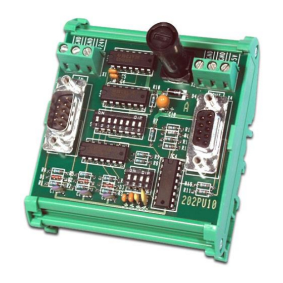
Open PCB version with plastic-housing for a simple snapping onto
top hat rails according to EN 60715
Input frequency max. 200 kHz
5 VDC power supply
motrona GmbH, Zeppelinstraße 16, DE - 78244 Gottmadingen, Tel. +49 (0) 7731 9332-0, Fax +49 (0) 7731 9332-30, info@motrona.com, www.motrona.com
PU202
Advertisement
Table of Contents

Subscribe to Our Youtube Channel
Related Manuals for Motrona PU202


Summary of Contents for Motrona PU202
- Page 1 Open PCB version with plastic-housing for a simple snapping onto top hat rails according to EN 60715 Input frequency max. 200 kHz 5 VDC power supply motrona GmbH, Zeppelinstraße 16, DE - 78244 Gottmadingen, Tel. +49 (0) 7731 9332-0, Fax +49 (0) 7731 9332-30, info@motrona.com, www.motrona.com...
-
Page 2: Table Of Contents
Legal notices: All contents included in this manual are protected by the terms of use and copyrights of motrona GmbH. Any reproduction, modification, usage or publication in other electronic and printed media as well as in the internet requires prior written authorization by motrona GmbH. -
Page 3: Safety Instructions And Responsibility
1. Safety Instructions and Responsibility 1.1 General Safety Instructions This operation manual is a significant component of the unit and includes important rules and hints about the installation, function and usage. Non-observance can result in damage and/or impairment of the functions to the unit or the machine or even in injury to persons using the equipment! Please read the following instructions carefully before operating the device and observe all safety and warning instructions! Keep the manual for later use. -
Page 4: Installation
Please find all respective hints and rules on www.motrona.com/download.html --> “[General EMC Rules for Wiring, Screening and Earthing]”. 1.4 Cleaning, Maintenance and Service Notes To clean the front of the unit please use only a slightly damp (not wet!), soft cloth. -
Page 5: Introduction
2. Introduction PU202 is designed for conversion of HTL impulse signals (10 … 30 VDC) to RS422 Standard or TTL level, including complements. Also, the unit can translate different modes of direction control to the A / B quadrature mode (2 x 90°), which is required for the majority of controllers. -
Page 6: Construction, Dimensions
3. Construction and dimensions The unit is designed as a PCB with a plastic-housing for a simple snapping onto top hat rails according to the EN 60715 norm. The impulse input are available on a 9-pin SUB-D-connector (female). For power supply of the unit and of encoders, two 3-way screw terminals are available. Pu202_02d_oi_e.doc / Apr-16 Page 6 / 10... -
Page 7: Power Supply
4. Power Supply The unit does not possess its own power supply unit. It must be supplied by an external source with +5 VDC +/-10% (approx. 50mA), which can either be connected to the 9-position output connector or the screw terminals marked “GND” and “5V” (see connection diagram below). Pin 4 of the output connector is internally connected to the +5V screw terminal. -
Page 8: Modes Of Operation
6. Operation Modes The output signals are always the same, independent of the mode of operation, but the inputs may have different functions. The mode can be selected by the 8-position DIL-switch S2. The index pulse (Z) will only be converted to TTL-level, but not be affected by the mode setting. 6.1. -
Page 9: Output Signal
7. Output Signal The quadrature output operates with a phase displacement between signals A/A’ and B/B’. In case of a quadrature type input signal with 90° phase shifting according to 6.1, the output appears with the same displacement of 90°. However, with inputs according to and 6.3, the phase displacement at the output will be constant in time, therefore will correspond to 90°... -
Page 10: Technical Specifications
8. Technical Specifications Power supply: Input voltage: 5 VDC +/- 10 % Protection: reverse polarity protection and fuse (0, 315 A medium time lag) Ripple: ≤ 10 % Consumption: approx. 50 mA (unloaded) Connections: selectively by 1,5 mm² / AWG 16 screw terminal or 9-pin male SUB-D connector Encoder supply: Only external voltage:...
Need help?
Do you have a question about the PU202 and is the answer not in the manual?
Questions and answers