Table of Contents
Advertisement
Quick Links
control – motion –
SSI => Analogue and SSI => Serial
• Suitable for operation with all sensors and encoders using SSI interface
• Scalable analogue outputs +/- 10 volts, 0-20 mA and 4-20 mA proportional to the
sensor signal
• Serial RS232 and RS485 interface for serial readout of the encoder data
• Easy to set up by Teach function or by PC
• Linearisation facilities by freely programmable input-output curves
• Additional facilities as bit-blanking, round-loop-operation etc.
• 18–30 volts DC power supply, auxiliary voltage output 5 V DC for sensor supply
IV25101A_e.DOC / Feb-08
interface
IV 251
Signal Converter
Operating Instructions
ELEKTRO-TRADING sp. z o.o
Tel.
+48 (0-32) 734-55-72
Tel/Fax +48 (0-32) 734-55-70
E-Mail et@elektro-trading.com.pl
http://www.elektro-trading.com.pl
Page 1 / 25
Advertisement
Table of Contents

Subscribe to Our Youtube Channel
Related Manuals for Motrona IV 251


Summary of Contents for Motrona IV 251
- Page 1 E-Mail et@elektro-trading.com.pl http://www.elektro-trading.com.pl control – motion – interface IV 251 Signal Converter SSI => Analogue and SSI => Serial • Suitable for operation with all sensors and encoders using SSI interface • Scalable analogue outputs +/- 10 volts, 0-20 mA and 4-20 mA proportional to the sensor signal •...
- Page 2 It provides an extended range of functions with use of a few more parameters, but is otherwise practically 100% compatible to WD251 units for use with SSI absolute encoders. For applications using incremental encoders, please refer to our converter type ZU252. Version: Description: IV25101a/af/kk/hk/Feb.08 Version A5-motrona IV25101A_e.DOC / Feb-08 Page 2 / 25...
-
Page 3: Table Of Contents
Table of Contents 1. Introduction....................4 2. Terminal Assignments and Connections............5 2.1. Encoder connections with Master operation ............5 2.2. Encoder connections with Slave operation............6 2.3. Analogue outputs ....................6 2.4. Serial interface......................7 3. DIL switch settings..................8 4. Commissioning....................9 4.1. -
Page 4: Introduction
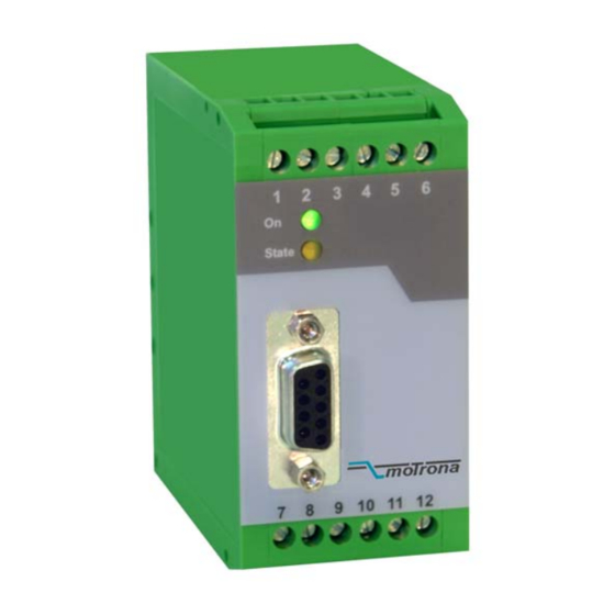
1. Introduction IV251 is a small and low-cost, but highly performing converter for industrial applications, where the information of a sensor or encoder with SSI interface needs to be converted to an analogue signal or to a serial RS232/485 data format. The unit has been designed as a compact module with 12 screw terminals and a 9-position SUB-D connector (female). -
Page 5: Terminal Assignments And Connections
2. Terminal Assignments and Connections The subsequent diagram shows the assignment of the screw terminals. We recommend to connect the Minus wire of the power supply to earth potential. GND terminals 4, 6 and 12 are connected internally. Depending on input voltage and load of the auxiliary voltage output, the total power consumption of the unit is about 200 mA. -
Page 6: Encoder Connections With Slave Operation
2.2. Encoder connections with Slave operation With this mode, the IV251 converter operates in parallel to another unit, acting as a „listener“ to the existing data communication. Quite according to need, the common potential of the master can be connected to terminal 12 (GND), or remain open for fully differential operation. -
Page 7: Serial Interface
PC, according to need. GND int. RS232 RS485 Sub-D-9 (female on unit site) RS232: Please connect only pins 2, 3 and 5 ! IV 251 120 Ohms 120 Ohms 120 Ohms 120 Ohms RS485- Bus IV 251... -
Page 8: Dil Switch Settings
3. DIL switch settings The DIL switch located on the top site of the unit provides customer-specific settings of desired operation modes. 1 2 3 4 5 6 7 8 Set Default: OFF:Unit loads default settings with every power-up cycle ON : No loading of default settings upon power-up. -
Page 9: Commissioning
4. Commissioning With basic applications, you can use the Teach procedure for commissioning of the unit. Extended functions need a PC for setup and are described later. 4.1. Self Test: Set all DIL switches according to your application and connect encoder and power supply to the unit. -
Page 10: The Set Input
• Your full scale position is allowed to be higher or lower than the zero position • More scaling facilities and linearization functions are available with PC setup • Teach min“ always refers to the initial output value defined by „Output mode“, i.e. -
Page 11: Serial Readout Of The Actual Encoder Position
PC is required. IV251 uses the DRIVECOM communication standard according to ISO 1745. Details about this protocol can be found in our file Serpro1a.doc which is available for motrona download on the homepage. The serial access code for the actual encoder position is „ :8 „... -
Page 12: Pc Setup Using The Operator Software Os32
You can download this software and full instructions, free of charge, from our homepage www.motrona.de • Connect your PC to the converter, using a serial RS232 cable like shown in section 2.4 of this manual. Make sure, the cable only connects pins 2, 3 and 5. -
Page 13: Parameter Settings
7. Parameter Settings 7.1. Display Settings: X Operand, / Operand, +/-Operand: These operands serve for conversion of the position information transmitted by the encoder into other engineering units like millimeters or inches etc. This conversion only refers to the numeric readout value by serial link, but does not affect the scaling of the analogue output. - Page 14 The following drawings explain the coherence between original encoder data, Round-Loop setting, SSI-Offset and Direction register. 8192 Original encoder signal Encoder 13Bit Direction = 0 SSI-Offset = 1024 Round-Loop = 2048 Round-Loop signal 2048 T-Max 1024 T-Min degrees SSI-Offset = 1024 Round-Loop= 2048 Volt Analogue Output (Output Mode = 1)
- Page 15 • Every change of the Round-Loop setting requires new entry of Teach-Min, Teach-Max and Offset values • With use of the Round-Loop function it is also possible to change the counting direction of the encoder, by setting the Direction bit correspondingly •...
-
Page 16: Ssi Specific Settings
7.3. SSI Specific Settings: SSI Low Bit: Defines the lowest bit (LSB) for evaluation, when the bit blanking function is used. Must be set to “01” for evaluation of the full encoder range. SSI High Bit: Defines the highest bit (MSB) for evaluation, when the bit blanking function is used. Must be set to the total number of encoder bits for evaluation of the full encoder range. - Page 17 SSI Baud Rate: Sets the communication speed of the SSI interface with SSI encoders. Setting range: 100 Hz to 1MHz. You are free to set any desired frequency between 0.1 kHz and 1000.0 kHz. For technical reasons however, in the upper frequency range with Master operation, the unit will only generate one of the following frequencies accurately: 1 000,0 kHz 888,0 kHz...
- Page 18 Analogue Analogue Update Update Auswertung SSI-Telegram SSI-Telegram Calculations 0msec 1msec 2msec 3msec SSI Wait Time = 3 msec • The shortest possible time for equidistant updating is 1.3 msec, due to internal processing times (SSI Wait Time set to 0.001) •...
-
Page 19: Ssi Error Settings
7.4. SSI Error Settings: SSI Error Bit: Defines the position of the error bit, if available with the encoder you use. Errors indicated by the encoder can be read out via serial code ;9 (semicolon nine, error indication = 2000hex). In case of an error, on your PC screen, the “Error Bit active”... - Page 20 Serial Baud Rate: Setting Baud 9600 4800 2400 1200 19 200 38 400 * = Factory setting Serial Format: Setting Data bits Parity Stop bits even even none none even none none * = Factory setting IV25101A_e.DOC / Feb-08 Page 20 / 25...
-
Page 21: Free Programmable Linearization
8. Free Programmable Linearization This programmable feature allows the user to convert a linear motion to a non-linear analogue output and vice-versa. There are 16 programmable interpolation points available, which can be set in any desired distance over the full conversion range. Between two points, the unit uses linear interpolation. - Page 22 You can visualize your curve on the PC screen or by means of an external oscilloscope. For this, select TOOLS, then TEST and there „Analogue Voltage Function“. The unit will now simulate a repeating motion of the encoder over the full range and generate the analogue signal accordingly.
-
Page 23: Testing Functions
9. Testing Functions When you select TEST from the TOOLS menu, you are able to verify the following data, by clicking to the corresponding field: • Actual encoder position • DIL switch settings • Internal supply voltages • Analogue output state Furthermore, the following registers can be recorded by using the monitor function: IV25101A_e.DOC / Feb-08 Page 23 / 25... -
Page 24: Dimensions And Specifications
10. Dimensions and Specifications 40 mm 91 mm ( 3.583’’ ) ( 1.575’’ ) 74 mm ( 2.913’’ ) Front view Side view Top view Power Supply 18...30 VDC Power consumption about 170 mA at 18V (+5.5V not connected) about 120 mA at 30V Inputs (SSI) TTL differential, RS-422 standard (1.0 MHz) SSI Format... -
Page 25: Parameter-List
11. Parameter-List Parameter Min. value Max. value Default Positions Char. Serial Code X Operand -10.0000 +10.0000 1.0000 +/- 6 / Operand 10.0000 1.0000 +/- Operand -99999999 99999999 +/- 8 Teach Minimum -99999999 +99999999 +/- 8 Teach Maximum -99999999 +99999999 10000 +/- 8 Round Loop 99999999...
Need help?
Do you have a question about the IV 251 and is the answer not in the manual?
Questions and answers