Table of Contents
Advertisement
Quick Links
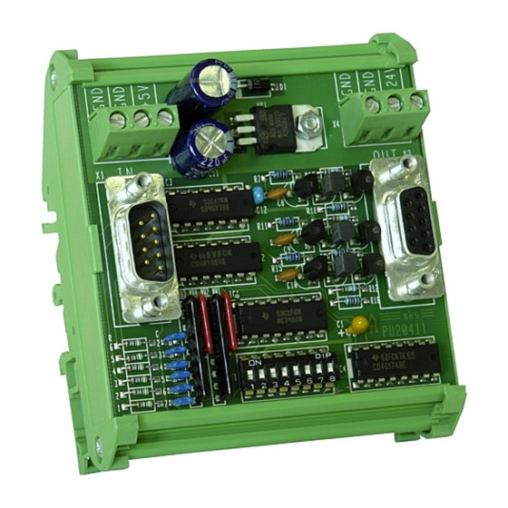
control – motion –
Level Converter and Direction Signal Generator
R S422 , 5V TTL
In puts:
A
/A
B
/B
/Z
PU20402a_e.DOC / Feb-08
interface
PU 204
Outputs: HTL 10-30V
A
B
Z
A
PU
204
Z
Z
Z
Operating Instructions
Qua drature
(2 x 90°)
Impulse s forw ard
Impulse s reverse
ELEKTRO-TRADING sp. z o.o
Tel.
+48 (0-32) 734-55-72
Tel/Fax +48 (0-32) 734-55-70
E-Mail et@elektro-trading.com.pl
http://www.elektro-trading.com.pl
Static directi on sig nal
Se para te channels
fo rward /reverse
Page 1 / 8
Advertisement
Table of Contents

Related Manuals for Motrona PU 204


Summary of Contents for Motrona PU 204
- Page 1 Tel. +48 (0-32) 734-55-72 Tel/Fax +48 (0-32) 734-55-70 E-Mail et@elektro-trading.com.pl http://www.elektro-trading.com.pl control – motion – interface PU 204 Level Converter and Direction Signal Generator Outputs: HTL 10-30V Qua drature R S422 , 5V TTL In puts: (2 x 90°) Static directi on sig nal...
- Page 2 Safety Instructions • This manual is an essential part of the unit and contains important hints about function, correct handling and commissioning. Non-observance can result in damage to the unit or the machine or even in injury to persons using the equipment! •...
-
Page 3: Table Of Contents
Table of Contents Introduction..................4 Construction, Dimensions ..............4 Power Supply ..................5 Setting of the Direction Signal ............6 4.1. Indication of direction by phase displacement (quadrature pulses) .....6 4.2. Indication of direction by static direction output ..........6 4.3. Separate channels for forward and reverse pulses ..........6 Connection of the Impulse Input ............ -
Page 4: Introduction
1. Introduction PU204 is designed to convert impulse levels from a TTL or RS422 format to a 10-30 V HTL format. At same time, the unit is suitable to convert the information of direction from the quadrature format to other usual standards like shown on the title page. For vice-versa conversion of level and direction signal, see type PU202. -
Page 5: Power Supply
3. Power Supply The unit needs a 10-30 VDC supply. The level of the supply voltage automatically determines also the level of the output swing (24V supply will cause pulse output with 24V level also). The supply voltage can either be applied to the screw terminals marked “GND” and “+24V”, or also via the female Sub-D-9 output connector, using pin 5 (GND) and pin 4 (+24V). -
Page 6: Setting Of The Direction Signal
4. Setting of the Direction Signal The unit, at the output, can use three different modes to indicate the sense of rotation. Output modes can be selected by the 8-position DIL switch on the print: 4.1. Indication of direction by phase displacement (quadrature pulses) 90°... -
Page 7: Connection Of The Impulse Input
5. Connection of the Impulse Input 5.1. Where at the input you use a shaft encoder which needs to be supplied by the PU204 unit: • Set DIL-switches 7 + 8 to “ON”. • Supply the encoder from pins 4 and 5. •... -
Page 8: Technical Specifications
6. Technical Specifications Power Supply 10 - 30 V DC Current consumption 85 mA (with 24V input, without encoder supply) Encoder Supply + 5 V / 100 mA (switch selectable) Max. frequency 200 kHz Input RS422 or TTL A, /A, B, /B, Z, /Z Output HTL, push/pull, A, B, Z / 10 - 30V, 30 mA each line Propagation delay...
Need help?
Do you have a question about the PU 204 and is the answer not in the manual?
Questions and answers