Table of Contents
Advertisement
Operating Manual
Pulse splitters for incremental encoders with and without potential separation
Product features:
•
Power supply from 10 up to 30 VDC
•
1 encoder input for channels A, /A, B, /B, Z, /Z
•
Input levels selectable between RS422, TTL and HTL
•
Optionally types with 2, 4 or 8 outputs with or without potential separation available (see below)
•
Output levels are specified by external power supply
•
Short-circuit proof +5VDC and +24VDC encoder supply
Available devices:
• GV224:
• GV228:
• GV228/EV:
• GT222:
• GT224:
• GT228:
• GT228/ET:
motrona GmbH, Zeppelinstraße 16, DE - 78244 Gottmadingen, Tel. +49 (0) 7731 9332-0, Fax +49 (0) 7731 9332-30, info@motrona.com, www.motrona.com
GV224 / GV228
GT222 / GT224 / GT228
Pulse splitter with 1 encoder input and 4 outputs
Pulse splitter with 1 encoder input and 8 outputs
Pulse splitter with 1 encoder input and 8 outputs
with extension option for 4 or 8 outputs (EV224 / EV228)
Pulse splitter with 1 encoder input and 2 potential separated outputs
Pulse splitter with 1 encoder input and 4 potential separated outputs
Pulse splitter with 1 encoder input and 8 potential separated outputs
Pulse splitter with 1 encoder input and 8 potential separated outputs
with extension option for 4 or 8 potential separated outputs (ET224 / ET228)
Advertisement
Table of Contents

Related Manuals for Motrona GV224


Summary of Contents for Motrona GV224
- Page 1 Pulse splitter with 1 encoder input and 8 potential separated outputs with extension option for 4 or 8 potential separated outputs (ET224 / ET228) motrona GmbH, Zeppelinstraße 16, DE - 78244 Gottmadingen, Tel. +49 (0) 7731 9332-0, Fax +49 (0) 7731 9332-30, info@motrona.com, www.motrona.com...
- Page 2 GV224_01a/March 22/tgo/mbo First edition GV22x / GT22x Legal notices: All contents included in this manual are protected by the terms of use and copyrights of motrona GmbH. Any reproduction, modification, usage or publication in other electronic and printed media as well as in the internet requires prior written authorization by motrona GmbH.
-
Page 3: Table Of Contents
1.4. EMC Guidelines 1.5. Cleaning, Maintenance and Service Notes Compatibility Hint Introduction and Block Diagram 3.1. Block diagram GV224 und GV228 3.2. Block diagram GT222 / GT224 und GT228 Electrical Connections und LED Function 4.1. Power Supply and LEDs 4.2. -
Page 4: Safety Instructions And Responsibility
1. Safety Instructions and Responsibility 1.1. General Safety Instructions This operation manual is a significant component of the unit and includes important rules and hints about the installation, function and usage. Non-observance can result in damage and/or impairment of the functions to the unit or the machine or even in injury to persons using the equipment! Please read the following instructions carefully before operating the device and observe all safety and warning instructions! Keep the manual for later use. -
Page 5: Installation
1.3. Installation The device is only allowed to be installed and operated within the permissible temperature range. Please ensure an adequate ventilation and avoid all direct contact between the device and hot or aggressive gases and liquids. Before installation or maintenance, the unit must be disconnected from all voltage-sources. Further it must be ensured that no danger can arise by touching the disconnected voltage- sources. -
Page 6: Emc Guidelines
Run signal and control cables apart from power lines and other cables emitting • electromagnetic noise. Please also refer to motrona manual “General Rules for Cabling, Grounding, Cabinet Assembly”. You can download that manual by the link https://www.motrona.com/en/support/general-certificates.html 1.5. Cleaning, Maintenance and Service Notes To clean the front of the unit please use only a slightly damp (not wet!), soft cloth. -
Page 7: Compatibility Hint
2. Compatibility Hint The GV220 and GT220 series are the successor models of the GV460 and GV480 family of pulse splitters, which have proven themselves thousand times. The new pulse splitters are able to largely replace the previous models functionally. However, there are minor differences in the wiring, the DIL switch setting and the potential separating. - Page 8 Housing: Dimensions (BxHxT): Dimensions (BxHxT): GV224/GT222/GT224: 34 x 100 x 131 mm / 72 x 144 x 60,5 mm 1,34 x 3,94 x 5,16 inches (w x h x d) 2,86 x 4,89 x 2,38 inches (w x h x d) (without connectors) (without connectors &...
-
Page 9: Introduction And Block Diagram
3. Introduction and Block Diagram GV224 and GV228 as well as GT222, GT224 and GT228 represent a series of incremental encoder splitters with a most compact, space-saving design and with most versatile technical features. All models are fully identical except for the number of output channels and any potential separation between input and output. -
Page 10: Block Diagram Gv224 Und Gv228
3.1. Block diagram GV224 und GV228 3.2. Block diagram GT222 / GT224 und GT228 Gv224_01a_oi_e.docx / Okt-22 Page 10 / 17... -
Page 11: Electrical Connections Und Led Function
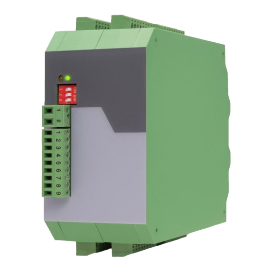
4. Electrical Connections und LED Function 4.1. Power Supply and LEDs The device is supplied with 10 to 30 VDC about the 2-pin screw terminal strip (X1) on the front of the device. The current consumption is approx. 25 mA (no-load operation). The upper LED (green) signals that power is applied to the unit. -
Page 12: Impuls Inputs
4.3. Impuls Inputs The encoder signal to be distributed is applied to the 9-pin input terminal on the front panel (X2). The desired input level as well as the desired signal format of the pulse inputs can be set accordingly at the front DIL switch and always apply to all channels A, B and Z. An individual setting of the individual channels is not possible. -
Page 13: Impuls Outputs
4.4. Impuls Outputs All outputs provide the non-inverted and the inverted signals at any time, even when on the input side the inverted signals are not available. The potential situation between the outputs and other circuits is clearly explained by the block diagrams in chapter 3. -
Page 14: Technical Specifications
500 kHz at HTL Differential max. 250kHz at SE TTL / SE HTL Connections: screw terminal, 1,5 mm² / AWG16 Incremental outputs: Number of outputs: 2 (GT222), 4 (GT224/GV224) resp. 8 (GT228/GV228), Output logic: push-pull Signal levels: 5 … 30 V (can be supplied by respective ext. - Page 15 -30 °C … +75° C / -22 °F … +167 °F (not condensing) Failure rate: MTBF in years: GT222: 131,7 a (continuous operation at GV224: 120,9 a / GT224: 102,0 a 60 °C / 140 °F) GV228: 85,4 a / GT228: 67,7 a Conformity & standards: EMC 2014/30/EU:...
-
Page 16: Dimensions
6. Dimensions GV224 / GT222 / GT224 GV228 / GT228 Gv224_01a_oi_e.docx / Okt-22 Page 16 / 17... - Page 17 EV224 / EV228 ET224 / ET228 Extension modules for pulse splitters with and without potential separation Product features: • Supply voltage via bus connector • Encoder input via bus connector • Optionally 4 or 8 additional outputs with or without potential separation (see below) •...
Need help?
Do you have a question about the GV224 and is the answer not in the manual?
Questions and answers