Table of Contents
Advertisement
Operating Manual
Level converter, direction signal decoder and programmable impulse divider
Features:
Level conversion from TTL / RS 422 to HTL 10 ... 30 V and vice versa
Programmable divider for error- free and position-true division of
quadrature encoder Signals (A, B, 90°)
Separate marker pulse divider with individual settings
300 kHz of maximum frequency
Push-pull outputs for direct PLC interfacing
18 ... 30 VDC power supply
motrona GmbH, Zeppelinstraße 16, DE - 78244 Gottmadingen, Tel. +49 (0) 7731 9332-0, Fax +49 (0) 7731 9332-30, info@motrona.com, www.motrona.com
IT251
Advertisement
Table of Contents

Related Manuals for Motrona IT251


Summary of Contents for Motrona IT251
- Page 1 300 kHz of maximum frequency Push-pull outputs for direct PLC interfacing 18 ... 30 VDC power supply motrona GmbH, Zeppelinstraße 16, DE - 78244 Gottmadingen, Tel. +49 (0) 7731 9332-0, Fax +49 (0) 7731 9332-30, info@motrona.com, www.motrona.com...
-
Page 2: Table Of Contents
Legal notices: All contents included in this manual are protected by the terms of use and copyrights of motrona GmbH. Any reproduction, modification, usage or publication in other electronic and printed media as well as in the internet requires prior written authorization by motrona GmbH. -
Page 3: Safety Instructions And Responsibility
1. Safety Instructions and Responsibility 1.1. General Safety Instructions This operation manual is a significant component of the unit and includes important rules and hints about the installation, function and usage. Non-observance can result in damage and/or impairment of the functions to the unit or the machine or even in injury to persons using the equipment! Please read the following instructions carefully before operating the device and observe all safety and warning instructions! Keep the manual for later use. -
Page 4: Installation
Please find all respective hints and rules on www.motrona.com/download.html --> “[General EMC Rules for Wiring, Screening and Earthing]”. 1.4. Cleaning, Maintenance and Service Notes To clean the front of the unit please use only a slightly damp (not wet!), soft cloth. -
Page 5: Introduction
2. Introduction IT 251 has been designed as a universal encoder interface for use with incremental encoder signals. The unit is suitable to solve the following applications: Level conversion from TTL / RS422 to HTL and vice-versa Division of quadrature encoder pulses, with adjustable division rate from 1:1 to 1:4096 ... -
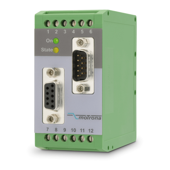
Page 6: Connections And Terminal Assignments
4. Connections and Terminal Assignments For frequency input, either the RS 422 inputs (D-SUB) or the 10 … 30 V HTL inputs can be used. The other inputs, which are not in use, must remain unconnected or must be disabled by corresponding DIL switch setting. - Page 7 It251_02c_oi_e.doc / Apr-16 Page 7 / 16...
-
Page 8: Basic Switch Settings
5. Basic Switch Settings Upon commissioning, some basic settings must be done by switch DIL4. These settings select one of the possible standards for expressing the direction of rotation on inputs and outputs. Also the potential of the metallic housings of the SUB-D-connectors can be set, and the inputs can be enabled or disabled (RS422 signals or HTL signals) Changes of the DIL switch positions will become active only after the next power-up of the unit! - Page 9 Configuration DIL4 on on Output direction on off standard off on on on Input direction on off standard off on Connects the metallic housing of SUB-D-connector “RS422 Input” to terminal 12 Metallic housing of the SUB-D-connector “RS422 Input” is potential-free Connects the metallic housing of SUB-D-connector “RS422 Output”...
- Page 10 this information, even when the phase is barely visible on an oscilloscope. For this kind of application, please set the A/B delay time by DIL switch 2, with consideration of your maximum output frequency. For division rates higher than 1:1, the phase displacement gets more and more close to a real 90º...
-
Page 11: Setting Of The Impulse Division Rate
6. Setting of the Impulse Division Rate The incremental division rate for the A/B input pulses can be set by means of switch DIL1 and by positions 1 – 4 of switch DIL2. The marker pulse Z uses a separate divider and marker division is described later. The switch positions use a binary code like shown in the subsequent list. -
Page 12: Index Pulse Divider (Marker Pulse Z)
7. Index Pulse Divider (Marker Pulse Z) 7.1. Unchanged index pulse (bypass) When you like to just bypass the index pulse from the input to the output (without any changes of frequency, position and pulse width), please use the following DIL switch settings: DIL3 DIL2 8 7 6 5 4 3 2... -
Page 13: Setting Of The Division Rate Of The Index Divider
7.3. Setting of the division rate of the index divider These settings use the same rules and codes as shown with the main divider (see section 6) Index Divider [Z] DIL3 on = log.0, off = log.1 Binary value 1 : 1 1 : 2 1 : 3 1 : 4... - Page 14 DIL2 Enlarged index pulse (one full encoder revolution) The pulse width of the enlarged output index pulse corresponds to the distance between two input index pulses (with index divider > 1 only). Index pulse width adapted to output frequency (1/4 output period) DIL2 (only applicable with quadrature input A/B, 90°) off*) The pulse width corresponds to 1/4 of one period of the output frequency...
-
Page 15: Technical Specifications
8. Technical Specifications Power supply: Input voltage: 18 … 30 VDC Protection circuit: reverse polarity protection Ripple: ≤ 10 % at 24 VDC Consumption: approx. 250 mA (at 18 V) (unloaded encoder supply) approx. 150 mA (at 30 V) Connections: screw terminal, 1.5 mm²... -
Page 16: Dimensions
9. Dimensions 91mm (3.583’’) 40 mm (1.575’’) 74 mm (2.193’’) Front view Side view It251_02c_oi_e.doc / Apr-16 Page 16 / 16...
Need help?
Do you have a question about the IT251 and is the answer not in the manual?
Questions and answers