Table of Contents
Advertisement
Quick Links
Operating Manual
Product features:
Various user modes: Programmable V / f characteristics, motorized
potentiometer function, cyclic frequency output curves etc.
Analog input configurable for voltage or current operation
Frequency outputs up to 100 kHz (HTL) resp. 500 kHz (RS422)
Very fast conversion time of approx. 1 ms
RS232 and RS485 interface for serial readout of the
conversion result and other internal registers
Adjustable floating average filter as well as operator
programmable linearization curves
Printer mode for automatic data transfer via serial interface
Power supply 18 to 30 VDC
motrona GmbH, Zeppelinstraße 16, DE - 78244 Gottmadingen, Tel. +49 (0) 7731 9332-0, Fax +49 (0) 7731 9332-30, info@motrona.com, www.motrona.com
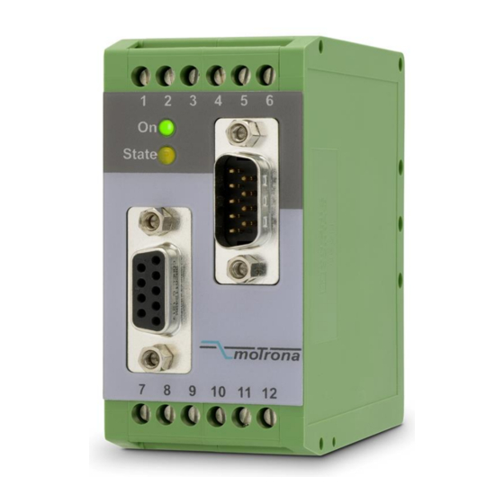
UF251
Signal converter analog - frequency / serial
Advertisement
Table of Contents

Subscribe to Our Youtube Channel
Related Manuals for Motrona UF251


Summary of Contents for Motrona UF251
- Page 1 Printer mode for automatic data transfer via serial interface Power supply 18 to 30 VDC motrona GmbH, Zeppelinstraße 16, DE - 78244 Gottmadingen, Tel. +49 (0) 7731 9332-0, Fax +49 (0) 7731 9332-30, info@motrona.com, www.motrona.com...
- Page 2 Legal notices: All contents included in this manual are protected by the terms of use and copyrights of motrona GmbH. Any reproduction, modification, usage or publication in other electronic and printed media as well as in the internet requires prior written authorization by motrona GmbH.
-
Page 3: Table Of Contents
Table of Contents 1. Safety Instructions and Responsibility ............4 General Safety Instructions ..................... 4 Use according to the intended purpose................4 Installation ........................5 Cleaning, Maintenance and Service Notes ..............5 2. Introduction ....................6 3. Terminal Assignment and Connections ............7 3.1. -
Page 4: Safety Instructions And Responsibility
1. Safety Instructions and Responsibility 1.1 General Safety Instructions This operation manual is a significant component of the unit and includes important rules and hints about the installation, function and usage. Non-observance can result in damage and/or impairment of the functions to the unit or the machine or even in injury to persons using the equipment! Please read the following instructions carefully before operating the device and observe all safety and warning instructions! Keep the manual for later use. -
Page 5: Installation
For placement, wiring, environmental conditions as well as shielding and earthing/grounding of the supply lines the general standards of industrial automation industry and the specific shielding instructions of the manufacturer are valid. Please find all respective hints and rules on www.motrona.com/download.html --> “[General EMC Rules for Wiring, Screening and Earthing]”. -
Page 6: Introduction
“UP-DOWN” or is determined by the polarity of the input signal. In “Motorized Potentiometer” Function Mode the UF251 can output a programmable frequency curve, under control of inputs “UP” and “DOWN”. -
Page 7: Terminal Assignment And Connections
3. Terminal Assignment and Connections Connect the power supply voltage to terminal 5 (+) and 6 (-). We recommend to tie the Minus wire of the power supply to earth potential. Terminals 4 (AGND) and 6 (GND) are connected internally. Depending on the power voltage level, the current consumption of the unit is approximately 120 to 180 mA. -
Page 8: Control Inputs
3.2. Control Inputs The unit provides two digital HTL inputs for control of the output frequency. The function of these inputs depends on the mode of operation. For properties and electrical specifications see the diagram below. Control Inputs: Properties and principle of circuit Max. -
Page 9: Serial Interface
3.4. Serial Interface The unit provides a RS232 interface and a RS485 interface. However, only one of both can be used at a time. Serial communication allows to read out the conversion result and to set parameters and variables by PC, according to need. The serial interface configuration is selected by DIL switch position 1. -
Page 10: Dil Switch Settings
4. DIL Switch Settings The DIL switch located on the top site of the unit provides customer-specific settings of desired operation modes. The switch settings below show normal operating mode with current input and freely adjustable frequency range. No default values will be loaded, the serial link is set to RS232 format and to printer transmission mode. -
Page 11: Setup Procedure
5. Setup Procedure All basic functions of the converter can easily be set up by the DIL switches, without use of a PC. For programming of advanced functions by PC see chapter 7. Self test: Upon power up, both front LED’s must be lit first, and the yellow status LED must switch off after the self test has been concluded successfully (approx.1 sec.). - Page 12 With the standard resolution mode there is an auxiliary output frequency divider available (programmable by register “Output Divider”). By well-aimed selection of the settings of “High Frequency” and “Output Divider” it is possible to optimize the overall accuracy and the dead band around zero. For instance, to improve accuracy, we can decrease “High Frequency”...
-
Page 13: Motorized Potentiometer Mode
For fine tuning of the input signal scaling it is possible to use the monitor function of the PC software. If you like to do this, set register “Average” to 6 to activate average mode and smooth the input signal. The monitor now will show very stable values of the analog input (register code :5), which you can use to set your “High Voltage”... -
Page 14: Readout Of Register Values Via Serial Interface
For setting of serial communication parameters etc., you must however apply PC set-up anyway, like shown later. UF251 uses the DRIVECOM communication protocol according to the ISO 1745 standard. Details about the protocol can be found in our file named SERPRO, available at any time on request. -
Page 15: Pc Setup With Use Of The Operator Software Os6.X
7. PC Setup with Use of the Operator Software OS6.x You can apply the full set of functions of the UF251 converter when using a PC and our operator software OS6.x for setup of the unit. The software is available for free download under www.motrona.com... -
Page 16: Displays And Soft Keys
8. Displays and Soft Keys The edit window for all unit parameters can be found on left hand side of the screen. The “INPUTS” field shows the soft keys to switch the control commands on or off. Display boxes in the RS column indicate when the corresponding command is set to ON by PC. Display boxes in the PI/O column indicate that the corresponding command is activated by external hardware. -
Page 17: Parameter Settings
9. Parameter Settings Parameter Description In-Out Value Setting These registers select the input and output signal range and define the voltage-frequency curve of the converter. With an input voltage of “Low Low Voltage: Voltage” the frequency value entered to “Low Frequency” will be High Voltage: generated and with an input voltage of “High Voltage”... - Page 18 Parameter Description Linearization Sets the mode of linearization. Mode: 0: Linearization off, registers P1 to P16 do not affect the output characteristics. 1: Linearization in a range of 0 – 100% 2: Linearization over full range –100% to +100% For full details about Linearization please refer to chapter 10. Direction This register controls the direction of the output frequency.
- Page 19 Parameter Description Output Divider: This register is only active with standard resolution (Parameter „High Resolution“ = 0). The frequency generated by the converter is divided by the value set to this register, before it appears at the output. Setting 1 results in no division (Frequency output 1:1). Setting 2 results in output frequency divided by 2 etc.
- Page 20 Parameter Description RS232/RS485 Setting With RS485 applications it is necessary to attach a specific address to each unit, since up to 32 units can be connected to the same bus. Unit Number: You can choose any address number between 11 and 99. Factory setting: 11 Unit addresses must not contain a “0“...
-
Page 21: Programmable Linearization
10. Programmable Linearization This programmable feature allows the user to convert a linear input signal to a non-linear output signal. There are 16 programmable x/y interpolation points available, which can be set in any desired distance over the full conversion range. Between two points, the unit uses linear interpolation. - Page 22 You can visualize your curve on the PC screen or by means of an external oscilloscope. When you like to do this, please select TOOLS / TEST / „Linear Function Test“. The unit will now simulate a repeating course over the full range and generate the output accordingly. Uf251_01d_oi_e.doc / Aug-16 Page 22 / 25...
-
Page 23: Test Functions
11. Test Functions When you select TEST from the TOOLS menu, you are able to verify the following data, by clicking to the corresponding field: Actual frequency DIL switch settings Internal supply voltages Frequency output state Uf251_01d_oi_e.doc / Aug-16 Page 23 / 25... -
Page 24: Dimensions
12. Dimensions 91mm (3.583’’) 40 mm (1.575’’) 74 mm (2.913’’) Front view Side view Top view Uf251_01d_oi_e.doc / Aug-16 Page 24 / 25... -
Page 25: Specifications
13. Specifications Power supply: Input voltage: 18 … 30 VDC Protection circuit: reverse polarity protection Ripple: ≤ 10 % at 24 VDC Consumption: approx. 120 mA … 170 mA Connections: screw terminal, 1.5 mm² / AWG 16 Analog input: Operation (switchable): Voltage, current or potentiometer Voltage: - 10 V …...
Need help?
Do you have a question about the UF251 and is the answer not in the manual?
Questions and answers