Table of Contents
Advertisement
Quick Links
Operating Manual
Signal converter FP210 / IP210 / PP210 / ZP210
Frequency (FP210)
SSI absolute value (IP210)
Start-Stop (PP210)
Pulse counter (ZP210)
Product features:
•
Multifunctional unit with several operating modes for incremental encoders or SSI absolute encoders
•
For incremental encoders:
Operating modes as frequency converter or position transducer (pulse counter)
Universal incremental inputs (HTL/TTL/RS422) for NPN/PNP/NAMUR encoders and sensors
Functions such as linkages (eg. A+B), scaling, filters,...
Input frequencies up to 1 MHz
•
For SSI absolute encoders:
Master or Slave operation with clock frequencies up to 1 MHz
For single turn and multi turn encoders with SSI formats from 10 ... 32 Bit
Functions such as bit suppression, round-loop function, scaling, ...
•
For absolute and magnetostrictive position encoder with Start-Stop-Interface:
Operating modes for master or slave, for position, angle and speed measurement
•
USB interface for configuration
•
Extremely short conversion times
•
Linearization with 24 control points
•
Auxiliary voltage output 5 and 24VDC for encoder supply
•
Compact rail housing to EN60715
•
Easy parameterization via user interface OS (Freeware)
motrona GmbH, Zeppelinstraße 16, DE - 78244 Gottmadingen, Tel. +49 (0) 7731 9332-0, Fax +49 (0) 7731 9332-30, info@motrona.de, www.motrona.de
Parallel (25 Bit)
→
Advertisement
Table of Contents

Related Manuals for Motrona FP210


Summary of Contents for Motrona FP210
- Page 1 Auxiliary voltage output 5 and 24VDC for encoder supply • Compact rail housing to EN60715 • Easy parameterization via user interface OS (Freeware) motrona GmbH, Zeppelinstraße 16, DE - 78244 Gottmadingen, Tel. +49 (0) 7731 9332-0, Fax +49 (0) 7731 9332-30, info@motrona.de, www.motrona.de...
- Page 2 Added parameter “Special PIN Function” Legal notices:: All contents included in this manual are protected by the terms of use and copyrights of motrona GmbH. Any reproduction, modification, usage or publication in other electronic and printed media as well as in the internet requires prior written authorization by motrona GmbH.
-
Page 3: Table Of Contents
Table of Contents Safety Instructions and Responsibility ................4 General Safety Instructions ......................4 Use according to the intended purpose ..................4 Installation ............................5 EMC Guidelines ..........................6 Cleaning, Maintenance and Service Notes..................6 Compatibility Hint ......................7 Introduction ........................8 Operating Mode .......................... -
Page 4: Safety Instructions And Responsibility
Safety Instructions and Responsibility General Safety Instructions This operation manual is a significant component of the unit and includes important rules and hints about the installation, function and usage. Non-observance can result in damage and/or impairment of the functions to the unit or the machine or even in injury to persons using the equipment! Please read the following instructions carefully before operating the device and observe all safety and warning instructions! Keep the manual for later use. -
Page 5: Installation
Installation The device is only allowed to be installed and operated within the permissible temperature range. Please ensure an adequate ventilation and avoid all direct contact between the device and hot or aggressive gases and liquids. Before installation or maintenance, the unit must be disconnected from all voltage-sources. Further it must be ensured that no danger can arise by touching the disconnected voltage-sources. -
Page 6: Emc Guidelines
• Run signal and control cables apart from power lines and other cables emitting electromagnetic noise. Please also refer to motrona manual “General Rules for Cabling, Grounding, Cabinet Assembly”. You can download that manual by the link https://www.motrona.com/en/support/general-certificates.html Cleaning, Maintenance and Service Notes To clean the front of the unit please use only a slightly damp (not wet!), soft cloth. -
Page 7: Compatibility Hint
Compatibility Hint This product is a successor model of the thousand fold proven converter type IP251. This converter is able to replace functionally the previous model; however some minor differences have to be observed with regard to the parameter settings. The main differences between this product and the respective predecessor model are listed below Differences of the IP210 compared to the previous model IP251 are: IP210... -
Page 8: Introduction
Introduction The device is designed as a signal converter with control inputs, which converts the corresponding sensor or encoder information into a parallel signal. It is also possible to convert serial data to a parallel format. Its extensive functions and operating modes make it universally applicable. Operating Mode Basically all functions have to be configured in the parameter menu. -
Page 9: Function Diagram
Function diagram Zp210_02a_oi_e.docx / Nov-20 page 9 / 58... -
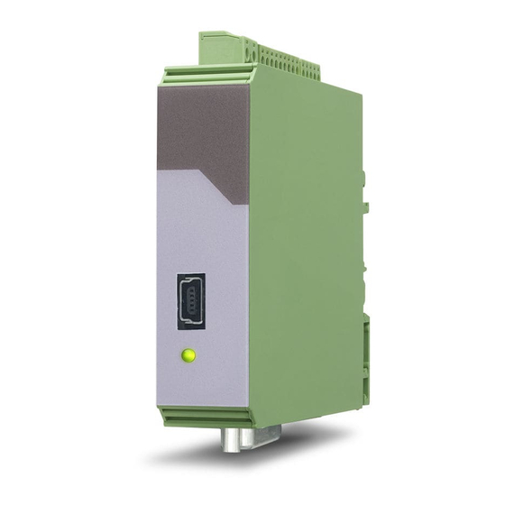
Page 10: Power - Led / Error Messages
Power – LED / Error messages The device has a green LED on its front foil. This lights up permanently as soon as the supply voltage of the device has been applied. If an error occurs, the LED flashes at 1 Hz. If the error no longer exists, the LED automatically lights up again permanently and the parallel output responds to the current result. - Page 11 Continuation “Power-LED / Error messages“: 0x00000020 Frequency (Input B) out of Maximum or minimum permissible input frequency range at input B has been exceeded or fallen below with the exponential filter setting used. (only for mode: Frequency) 0x00000040 Start/Stop Encoder Error No "start"...
-
Page 12: Electrical Connections
Electrical Connections The terminal screws should be tightened with a slotted screwdriver (blade width 2mm). DC Power Supply (X1) The unit accepts DC supply from 10 to 30 V at the terminals X1 1 and 2. The power consumption depends on the level of the supply voltage with aprox. 25 mA and the additional current required at the Auxiliary Voltage Output. -
Page 13: Incremental Encoder Input (X2)
Incremental encoder input (X2) Terminal X2 pins 3, 4, 5 and 6 provide a connection for various incremental signals. RS422 HTL DIFFERENTIAL HTL PNP HTL NPN Zp210_02a_oi_e.docx / Nov-20 page 13 / 58... - Page 14 Continuation “Incremental encoder input (X2)“: HTL NPN (NAMUR) TTL (PNP) Unconnected PNP inputs are always “LOW” and unconnected NPN inputs are always “HIGH”. All inputs are designed to receive impulses from electrical impulse sources. Notice for mechanical switching contacts: When exceptionally mechanical contacts are used, please connect an external capacitor between GND (-) and the corresponding input (+).
-
Page 15: Ssi-Absolute Encoder Input (X2)
SSI-Absolute encoder input (X2) At terminal X2 pin 1, 2, 3, 4 the SSI connection for the MODE MASTER is available. At terminal X2 pin 3, 4, 5, 6 the SSI connection for the MODE SLAVE is available. Connection for MODE Master: Zp210_02a_oi_e.docx / Nov-20 page 15 / 58... - Page 16 Continuation “SSI-Absolute encoder input (X2)“: Connection for MODE Slave: Zp210_02a_oi_e.docx / Nov-20 page 16 / 58...
-
Page 17: Start-Stop Encoder Inputs (X2)
Start-stop encoder inputs (X2) At terminal X2 - Pin 1+2 the RS422 connection for the init pulse in "MODE MASTER" is available. (Device generates Init pulse itself!). At terminal X2 - Pin 5+6 the RS422 connection for the init pulse in "MODE SLAVE" is available. (Init pulse is generated by an external device!). -
Page 18: Control Inputs (X3)
Control Inputs (X3) At terminal X3 pins 2,3 and 4 there are three control inputs with HTL PNP characteristic available. Control Input 1 (Ctrl. In 1) to Control Input 2 (Ctrl. In 2) are freely configurable in the COMMAND MENU and are used for functions to be triggered externally. eg. for resetting the measurement result or for freezing the parallel output. -
Page 19: Parallel Output (X5) / Com + (X3)
Parallel output (X5) / COM + (X3) The parallel outputs are 25 short-circuit proof push-pull outputs. The common, independent supply voltage of the outputs is applied to terminal X3 - pin 5 (COM +). The supply voltage at COM + should not exceed +27 V, otherwise the permanent short circuit restistance of the outputs can no longer be guaranteed. -
Page 20: Serial Interface (X4)
Continuation ”Data stable” – output”: Serial interface (X4) A serial USB interface (mini USB) is available at terminal X4. The USB interface can be used as follows: • For parameterization of the device during commissioning • To change parameters during operation •... -
Page 21: Parameter / Overview-Menu Structure
Parameter / Overview-Menu Structure The parameterization of the device is realized via the serial interface with a PC and the operating software OS. The link to the free download can be found on page 2. This section provides an overview of the menus and their parameters. The menu names are printed bold and the associated parameters are listed under the menu name. - Page 22 Continuation “Parameter / menu structure“: Menu / Parameter PARALLEL MENU PARALLEL MODE PARALLEL INV. PARALLEL VALUE PARALLEL UPDATE TIME (s) SPECIAL PIN FUNCTION COMMAND MENU INPUT 1 ACTION INPUT 1 CONFIG INPUT 2 ACTION INPUT 2 CONFIG INPUT 3 ACTION (FACTORY SETTINGS) INPUT 3 CONFIG (ACTIVE HIGH) LINEARISATION MENU P1(X)
-
Page 23: General Menu
General Menu MODE This parameter specifies the selected measuring function. NOT DEFINED Operating mode: Not defined, modulation and measurement results are zero FREQUENCY Operating mode: Frequency converter, incremental signals COUNTER Operating mode: Counter, incremental signals Operating mode: Absolute value converter, SSI signals (replaces IV251) START / STOP Operating mode: Start / Stop –... - Page 24 Continuation “General Menu“: LINEARIZATION MODE This parameter defines the linearization function. Observe notes in the appendix! No linearization 1 QUADRANT Linearization in the 1. quadrant 4 QUADRANT Linearization in all 4 quadrants BACK UP MEMORY (Note: Only relevant for MODE: "COUNTER"!) No back up memory –up by power failure Back up memory is active.
-
Page 25: Mode Frequency
Mode Frequency In this menu the operation is defined as a frequency converter (incremental signals). Depending on the selected operating mode, only channel A or both channels (channel A and channel B) are active. FREQUENCY MODE This parameter determines which frequency measurement mode is desired. A ONLY Single-channel frequency measurement (only for channel A) Frequency ratio of both channels (channel B / channel A). - Page 26 Continuation “Mode Frequency“: WAIT TIME 1 (S) This parameter defines the period time of the lowest frequency, accordingly the time between two rising signal edges on channel A detecting frequency 0 Hz. Frequencies with a period time higher than the set “WAIT TIME 1”...
- Page 27 Continuation “Mode Frequency“: AVERAGE FILTER 1 Selectable averaging or filter function for unstable frequencies at input A for smoothing the output at the parallel output. At settings 5 to 16, the device uses an exponential function. The time constant T (63%) corresponds to the sampling cycles. For example: If SAMPLING TIME = 0,1 s and AVERAGE FILTER = Exponential filter, T (63 %) = 2x SAMPLING TIME, after 0,2 seconds, 63% of the step size are reached.
- Page 28 Continuation “Mode Frequency“: SAMPLING TIME 2 (S) The set value corresponds to the minimum measuring time (for channel B) in seconds. The sampling time serves as a filter at irregular frequencies. This parameter directly influences the reaction time of the device. 0,001 Shortest Sampling time Default value...
- Page 29 Continuation “Mode Frequency“: AVERAGE FILTER 2 Selectable averaging or filter function for unstable frequencies at input B for smoothing the output at the parallel output. At settings 5 to 16, the device uses an exponential function. The time constant T (63%) corresponds to the sampling cycles. For example: If SAMPLING TIME = 0,1 s and AVERAGE FILTER = Exponential filter, T (63 %) = 2x SAMPLING TIME, after 0,2 seconds, 63% of the step size are reached.
-
Page 30: Mode Counter
Mode Counter In this menu, the operation is defined as a position transducer for incremental signals (pulse, sum, difference, up or down counter). Input A and B are active. COUNT MODE This parameter defines the counter operation. Input A is a counting input. A SINGLE Input B defines the counting direction: „LOW“... - Page 31 Continuation “Mode Counter: ROUND LOOP VALUE Defines the number of encoder steps if a round-loop function is desired. (Only for COUNT MODE: A SINGLE and A / B x 90) Round-loop function is turned off. … 99999999 Number of steps for the round-loop function. Zp210_02a_oi_e.docx / Nov-20 page 31 / 58...
-
Page 32: Mode Ssi
Mode SSI In this menu the operation is defined as absolute value converter (SSI signals). SSI MODE SSI Setting of the operating mode: Maser or Slave Depending on the SSI MODE, different terminals must be used for the SSI CLK! (Mode Master: Terminal X2 - Pin 1 and 2 / Mode Slave: Terminal X2 - Pin 5 and 6) MASTER Master-Mode: Clock for SSI encoder comes from the device... - Page 33 Continuation “Mode SSI“: LOW BIT (for bit blanking) Defines the lowest evaluated bit (MSB) for bit blanking. If all bits should be evaluated, LOW BIT must be set to 01. Smallest value … Highest value SSI OFFSET In the case of a „RESET/SET VALUE“ command (via control input or PC user interface) the not yet scaled, currently acquired position value (after bit suppression and possibly performed encoder zero offset) is transferred to the "SSI OFFSET"...
-
Page 34: Mode Start/Stop
Mode Start/Stop This menu defines the operating as Start / Stop – interface converter. INIT MODE Operating mode: Master or Slave Depending on the selected INIT MODE, different terminals must be used for the Init pulse! (Mode Master: terminal X2 – Pin 1 and 2 / Mode Slave: terminal X2 – Pin 5 and 6) MASTER Master-operation: Init pulse is generated by the device. - Page 35 Continuation “Mode Start/Stop“: CIRCUMFERENCE (mm) Setting the reference size (in "mm") for an angle measurement. The distance covered (e.g. circumference) at which the subsequent output value (ROUND LOOP VALUE) is to be generated must be set here. (Note: Only for OPERATIONAL MODE: "ANGLE") 00000.001 Smallest value 01000.000...
-
Page 36: Serial Menu
Serial Menu This menu defines the basic settings of serial interface. UNIT NUMBER This parameter defines serial device addresses. The addresses between 11 and 99 can be assigned to the devices. Addresses with zero are not allowed, there are used as broadcast addresses. Note: Device address is fixed to "11"... - Page 37 Continuation “Serial Menu“: SERIAL INIT This parameter defines the baud rate for the initialization to the user interface OS. With settings larger than 9600 the initialization time can be reduced. Note: The initialization values are always transmitted with 115200 Baud for the USB interface. Initialization with 9600 baud.
- Page 38 MODBUS Note: Modbus protocol cannot be selected via USB interface on this device! Modbus disabled Serial interface is using Lecom protocol (Motrona-default protocol) Modbus enabled: Serial interface is using Modbus RTU protocol 1 … 247 The set value is the Modbus address of the device.(N.A.) Zp210_02a_oi_e.docx / Nov-20...
-
Page 39: Parallel Menu
Parallel Menu In this menu the basic settings for the parallel output are defined. The parallel output always refers to the scaled "Measurement Result"! PARALLEL MODE Determines the output format of the parallel output and the source of the input data as follows: Parallel output format as binary code. - Page 40 Continuation “Parallel Menu“: SPECIAL PIN FUNCTION Determines the function of the 24. and 25. parallel output. (PIN24 + PIN25) DATA & DATA Pin 25 : Data output (Bit 25) Pin 24: Data output (Bit 24) ERROR & DATA Pin 25 : Error output (Active High) Pin 24: Data output (Bit 24) /ERROR &...
-
Page 41: Command Menu
Command Menu INPUT 1 ACTION (function Input 1) This parameter defines the function of the input “Ctrl. In 1”. static switching (level evaluation), INPUT CONFIG must be set to active LOW / HIGH (s) = dynamic switching (edge evaluation) ,INPUT CONFIG must be set to RISING/FALLING EDGE (d) = No function Mode “SSI”: Transfer of the currently detected position value... - Page 42 Continuation “Command Menu“: INPUT 1 CONFIG This parameter defines the switching characteristics of the input “Ctrl. In 1”. ACTIVE LOW Active at „LOW“ (static) ACTIVE HIGH Active at „HIGH“ (static) RISING EDGE Activate at rising edge (dynamic) FALLING EDGE Activate at falling edge (dynamic) INPUT 2 ACTION This parameter defines the control function of the input “Ctrl.
-
Page 43: Linearization Menu
Linearization Menu The linearization function is defined in this menu. The linearization function always refers to the scaled "Measurement Result"! Linearization description and examples are shown in the appendix. P1(X) … P24(X) X-coordinate of the linearization point. This is the value that the device would generate without linearization depending on the input signal. -99999999 Smallest X-coordinate Default value... -
Page 44: Appendix
All codes shown in the parameter SERIAL VALUE are available for serial readout by PC or PLC. The communication of Motrona-devices is based on the Drivecom protocol according to ISO 1745 or the Modbus RTU protocol. All protocol details can be found in our manual SERPRO (Drivecom) which is available for download from the homepage www.motrona.en... -
Page 45: Parameter List / Serial Codes
Parameter list / serial codes Menü Name Code Default GENERAL MENU MODE GENERAL MENU ENCODER PROPERTIES GENERAL MENU ENCODER DIRECTION GENERAL MENU FACTOR -99999999 99999999 GENERAL MENU DIVIDER -99999999 99999999 GENERAL MENU ADDITIVE VALUE -99999999 99999999 GENERAL MENU LINEARIZATION MODE GENERAL MENU BACKUP MEMORY GENERAL MENU... - Page 46 Continuation “Parameter list /serial codes“: Menu Name Code Default MODE START/STOP INIT MODE MODE START/STOP SAMPLING TIME (ms) 16000 4000 MODE START/STOP INIT PULSE TIME (µs) MODE START/STOP VELOCITY (m/s) 999999 280000 MODE START/STOP OPERATIONAL MODE MODE START/STOP OFFSET -99999999 99999999 MODE START/STOP CIRCUMFERENCE (mm)
- Page 47 Continuation “Parameter list /serial codes“: Menu Name Code Default LINEARIZATION MENU P3(Y) -99999999 99999999 LINEARIZATION MENU P4(X) -99999999 99999999 LINEARIZATION MENU P4(Y) -99999999 99999999 LINEARIZATION MENU P5(X) -99999999 99999999 LINEARIZATION MENU P5(Y) -99999999 99999999 LINEARIZATION MENU P6(X) -99999999 99999999 LINEARIZATION MENU P6(Y) -99999999 99999999...
- Page 48 Serial codes of commands: Serial Code Command RESET/SET FREEZE DISPLAY SSI ZERO POSITION RESET/SET COUNTER A RESET/SET COUNTER B LOCK COUNTER A LOCK COUNTER B RESET MIN/MAX FACTORY SETTINGS CLEAR LOOP TIME SERIAL PRINT ACTIVATE DATA STORE DATA TESTPROGRAM Zp210_02a_oi_e.docx / Nov-20 page 48 / 58...
-
Page 49: Linearization
Linearization The linearization function of this unit allows converting a linear input signal into a non-linear developing (or vice versa). There are 24 programmable x/y coordinates available, which can be set in any desired distance over the full conversion range. Between two coordinates, the unit uses linear interpolation. - Page 50 Application Example: The picture below shows a watergate where the opening is picked up by means of an incremental encoder. We would like to display the clearance of the gate "d", but the existing encoder information is proportional to the angular information φ. Zp210_02a_oi_e.docx / Nov-20 page 50 / 58...
-
Page 51: Reading Ssi-Value
Reading SSI-Value The received data is always filled to 32 bit data length. Zp210_02a_oi_e.docx / Nov-20 page 51 / 58... -
Page 52: Internal Processing And Calculation Of Ssi Data
Internal processing and calculation of SSI data Zp210_02a_oi_e.docx / Nov-20 page 52 / 58... - Page 53 Continuation “Internal processing and calculation of SSI data” Zp210_02a_oi_e.docx / Nov-20 page 53 / 58...
- Page 54 Continuation “Internal processing and calculation of SSI data” Zp210_02a_oi_e.docx / Nov-20 page 54 / 58...
-
Page 55: Operating Modes / Op Modes Of The Start/Stop Interface
Operating modes / OP modes of the Start/Stop interface The device supports the following operating modes: • MASTER - The Init pulse for the connected encoder is generated by the device. - The two Init connections (INIT OUT, /INIT OUT) are configured as outputs in this case. •... - Page 56 Continuation “Operating modes / OP modes of the Start/Stop interface” • SPEED (speed measurement) The speed is recorded and can be converted again into another unit using existing scaling parameters (Factor, Divider and Additive Value), if desired. Interpretation of the measurement result during speed measurement: The default setting ("FACTOR = 1", "DIVIDER = 1"...
-
Page 57: Dimensions
Dimensions Zp210_02a_oi_e.docx / Nov-20 page 57 / 58... -
Page 58: Technical Specifications
Technical Specifications: Technical Specifications Connections: Connector type: screw terminal, 1.5 mm² / AWG 16 25 pin SUB-D socket for parallel output Power supply (DC):: Input voltage: 10 … 30 VDC Protection circuit: reverse polarity protection Consumption: approx. 30 mA (unloaded) Fuse protection: extern: T 0.5 A Encoder supply:...
Need help?
Do you have a question about the FP210 and is the answer not in the manual?
Questions and answers