Table of Contents
Advertisement
Quick Links
Operating Manual
TTL / RS422 - HTL converter & direction signal generator without potential separation
Product Features:
Converts TTL / RS422 signals (A, /A, B, /B, Z, /Z ) to HTL with 10 ... 30 VDC level
Generates also a static HIGH / LOW direction signal or separate direction-pulses
from a directional 90° phase shifted A / B information
Open PCB version with plastic-housing for a simple snapping
onto top hat rails according to EN 60715
Input frequencies up to 200 kHz possible
10 ... 30 VDC power supply
motrona GmbH, Zeppelinstraße 16, DE - 78244 Gottmadingen, Tel. +49 (0) 7731 9332-0, Fax +49 (0) 7731 9332-30, info@motrona.com, www.motrona.com
PU204
Advertisement
Table of Contents

Subscribe to Our Youtube Channel
Related Manuals for Motrona PU204


Summary of Contents for Motrona PU204
- Page 1 EN 60715 Input frequencies up to 200 kHz possible 10 … 30 VDC power supply motrona GmbH, Zeppelinstraße 16, DE - 78244 Gottmadingen, Tel. +49 (0) 7731 9332-0, Fax +49 (0) 7731 9332-30, info@motrona.com, www.motrona.com...
-
Page 2: Table Of Contents
6. Connection of the Impulse Input ..............9 6.1. Where at the input you use a shaft encoder which needs to be supplied by the PU204 unit: .. 9 6.2. Where you use an encoder with separate supply, or the encoder simulation of a drive: ..9 6.3. -
Page 3: Safety Instructions And Responsibility
1. Safety Instructions and Responsibility 1.1 General Safety Instructions This operation manual is a significant component of the unit and includes important rules and hints about the installation, function and usage. Non-observance can result in damage and/or impairment of the functions to the unit or the machine or even in injury to persons using the equipment! Please read the following instructions carefully before operating the device and observe all safety and warning instructions! Keep the manual for later use. -
Page 4: Installation
Please find all respective hints and rules on www.motrona.com/download.html --> “[General EMC Rules for Wiring, Screening and Earthing]”. 1.4 Cleaning, Maintenance and Service Notes To clean the front of the unit please use only a slightly damp (not wet!), soft cloth. -
Page 5: Introduction
2. Introduction PU204 is designed to convert impulse levels from a TTL or RS422 format to a 10 … 30 V HTL format. At same time, the unit is suitable to convert the information of direction from the quadrature format to other usual standards like shown in the pulse diagram below. -
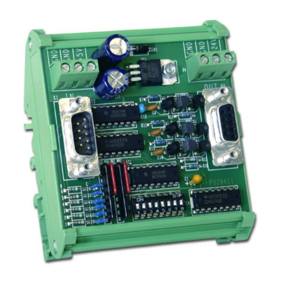
Page 6: Construction And Dimensions
3. Construction and Dimensions The unit is designed as a PCB with a plastic frame for direct and easy DIN rail mounting. The impulse inputs are available on a 9-pin SUB-D-connector (male). The outputs are available on a 9-pin SUB-D-connector (female). For power supply of the unit and of encoders, two 3-position screw terminals are available. -
Page 7: Power Supply
4. Power Supply The unit needs a 10 … 30 VDC supply. The level of the supply voltage automatically determines also the level of the output swing (24 V supply will cause pulse output with 24 V level also). The supply voltage can either be applied to the screw terminals marked “GND” and “+24V”, or also via the female SUB-D-9 output connector, using pin 5 (GND) and pin 4 (+24 V). -
Page 8: Setting Of The Direction Signal
5. Setting of the Direction Signal The unit, at the output, can use three different modes to indicate the sense of rotation. Output modes can be selected by the 8-position DIL switch on the print: 5.1. Indication of direction by phase displacement (quadrature pulses) 5.2. -
Page 9: Connection Of The Impulse Input
Set DIL-switches 7 + 8 to “ON”. Supply the encoder from pins 4 and 5. Connect the screen to the supply minus wire at the PU204 side (pin 5). 6.2. Where you use an encoder with separate supply, or the encoder simulation of a drive: ... -
Page 10: Technical Specifications
7. Technical Specifications Power supply: Input voltage: 10 … 30 VDC Protection: reverse polarity protection and fuse (0, 315 A medium time lag) Ripple: ≤ 10 % Consumption: approx. 85 mA (unloaded) Connections: selectively by 1.5 mm² / AWG 16 screw terminal or 9-pin female SUB-D connector Encoder supply: Output voltage:...
Need help?
Do you have a question about the PU204 and is the answer not in the manual?
Questions and answers