Table of Contents
Advertisement
Operating Manual
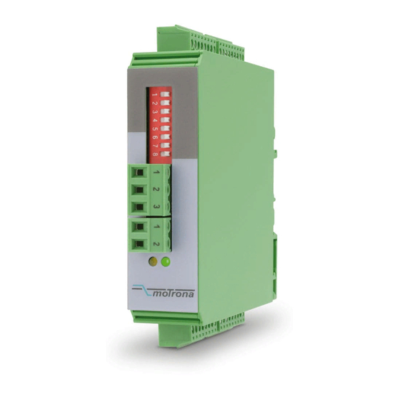
Encoder distributor, cross switcher and splitter for incremental encoder signals
Product Features:
Universal encoder interface, applicable as level converter, encoder splitter and cross switch
Two encoder inputs (A, /A, B, /B, Z, /Z), adjustable either to HTL, TTL or RS422 level
Suitable for quadrature, symmetrical, asymmetrical as well as single channel signals
Two signal outputs (A, /A, B, /B, Z, /Z), adjustable either to HTL, TTL or RS422 level
Contactless and bounce-free switch-over between the encoder channels, by
remote control signals
Auxiliary output 5 VDC for encoder supply
High frequency range up to 1 MHz
motrona GmbH, Zeppelinstraße 16, DE - 78244 Gottmadingen, Tel. +49 (0) 7731 9332-0, Fax +49 (0) 7731 9332-30, info@motrona.com, www.motrona.com
GV210
Advertisement
Table of Contents

Related Manuals for Motrona GV210


Summary of Contents for Motrona GV210
- Page 1 Contactless and bounce-free switch-over between the encoder channels, by remote control signals Auxiliary output 5 VDC for encoder supply High frequency range up to 1 MHz motrona GmbH, Zeppelinstraße 16, DE - 78244 Gottmadingen, Tel. +49 (0) 7731 9332-0, Fax +49 (0) 7731 9332-30, info@motrona.com, www.motrona.com...
- Page 2 Legal notices: All contents included in this manual are protected by the terms of use and copyrights of motrona GmbH. Any reproduction, modification, usage or publication in other electronic and printed media as well as in the internet requires prior written authorization by motrona GmbH.
-
Page 3: Table Of Contents
Table of Contents 1. Safety Instructions and Responsibility ............4 General Safety Instructions ................... 4 Use according to the intended purpose ..............4 Installation ......................5 Cleaning, Maintenance and Service Notes ............5 2. Applications ....................6 2.1. Dual level converter ....................6 2.2. -
Page 4: Safety Instructions And Responsibility
1. Safety Instructions and Responsibility 1.1 General Safety Instructions This operation manual is a significant component of the unit and includes important rules and hints about the installation, function and usage. Non-observance can result in damage and/or impairment of the functions to the unit or the machine or even in injury to persons using the equipment! Please read the following instructions carefully before operating the device and observe all safety and warning instructions! Keep the manual for later use. -
Page 5: Installation
Please find all respective hints and rules on www.motrona.com/download.html --> “[General EMC Rules for Wiring, Screening and Earthing]”. 1.4 Cleaning, Maintenance and Service Notes To clean the front of the unit please use only a slightly damp (not wet!), soft cloth. -
Page 6: Applications
2. Applications 2.1. Dual level converter RS422 or Control 1 HTL 10-30V HTL 10-30V = LOW or RS422 A, /A, B, /B, Z, /Z A, /A, B, /B, Z, /Z Out1 Out2 A, /A, B, /B, Z, /Z A, /A, B, /B, Z, /Z RS422 or HTL 10-30V Control 2... -
Page 7: Encoder Signal Switcher
2.3. Encoder signal switcher Both inputs can be individually set to either symmetric (differential) format using A, /A, B, /B, Z, /Z channels, or to asymmetric (single-ended) format using A, B, Z channels only. Acceptable input levels are RS422, TTL and HTL 10 … 30 V. The output standard can again be selected individually for each output. -
Page 8: Connection Diagram
3. Connection Diagram Output 1 Input 1 8 7 6 5 4 3 2 1 9 8 7 6 5 4 3 2 1 Terminal strip 8-pos. Terminal strip 9-pos. Connectors are mechanically coded and therefore not Control 1 interchangeable Control 2 Power supply Terminal strip 8-pos. -
Page 9: Asymmetric Ttl Inputs
A, B and Z may at any time also be independent single signals, e.g. from proximities, photocells etc. Since the level of every channel is selected individually (see DIL-switch), it is possible to use different levels on the inputs. Consequently it is e.g. possible to take the position information from the A, /A, B and /B channels of a RS422 encoder, but to add the corresponding Z index pulse as a HTL signal from a remote photocell With HTL signals, the switching threshold lies between 6.5 and 8 V. -
Page 10: The Front Leds
4. The Front LEDs The green LED is lit as soon as a power supply voltage is applied to the unit. The yellow LED indicates the state of the Control inputs and the basic function of the unit: Yellow LED off: Control1 and Control2 are either both LOW or both HIGH at the same time. In this case the unit operates as a splitter (both outputs are connected to the same input) Yellow LED on: Control1 and Control2 have different states. -
Page 11: Switch Settings
5. Switch Settings The DIL switch sets level and standard of inputs and outputs: 0=OFF DIL switch settings 1=ON Output 1: TTL / RS422 The output levels are 5 V with Output 1: HTL TTL setting and correspond to the power supply voltage with Output 2: TTL / RS422 HTL setting Output 2: HTL... -
Page 12: Dimensions
6. Dimensions 102 (4.016”) 22.5 (0.886”) 91 (3.583”) Side view Front view Top view Gv210_02f_oi_e.doc / 01-16 Page 12 / 13... -
Page 13: Technical Specifications
7. Technical Specifications Power supply: Input voltage: 12 … 30 VDC Protection circuit: reverse polarity protection Ripple: ≤ 10 % at 24 VDC Consumption: approx. 50 mA (unloaded) Connections: Connector type: screw terminals, 1.5 mm² Encoder supply Output voltages: 5.2 VDC und 10 …...
Need help?
Do you have a question about the GV210 and is the answer not in the manual?
Questions and answers