Table of Contents
Advertisement
Quick Links
Operating Manual
Universal signal converter: Analog (V/mA) - Incremental / SSI / RS232 / RS485
Product Features:
Analog input for voltage, current or potentiometer operation
Operation as frequency converter/-generator, positional / angular encoder or data
logging possible
Programmable curves with optionally repeating curve cycles
Frequency output (HTL or TTL level, max. 1 MHz) proportional to the input signal
Incremental output and SSI interface, for digital expression of linear or angular positions
Incremental direction signal A, B under control of input signal and parameter settings
Additional control functions similar to a motorized potentiometer
USB programming port and serial interface (RS232 / RS485)
Programmable marker resp. index pulse output (Z, /Z)
Power supply 12 to 30 VDC
motrona GmbH, Zeppelinstraße 16, DE - 78244 Gottmadingen, Tel. +49 (0) 7731 9332-0, Fax +49 (0) 7731 9332-30, info@motrona.com, www.motrona.com
UZ210
Advertisement
Table of Contents

Related Manuals for Motrona UZ210


Summary of Contents for Motrona UZ210
- Page 1 USB programming port and serial interface (RS232 / RS485) Programmable marker resp. index pulse output (Z, /Z) Power supply 12 to 30 VDC motrona GmbH, Zeppelinstraße 16, DE - 78244 Gottmadingen, Tel. +49 (0) 7731 9332-0, Fax +49 (0) 7731 9332-30, info@motrona.com, www.motrona.com...
- Page 2 Hint supplemented: Only RS232 or RS485 (not both at the same time). Legal notices: All contents included in this manual are protected by the terms of use and copyrights of motrona GmbH. Any reproduction, modification, usage or publication in other electronic and printed media as well as in the internet requires prior written authorization by motrona GmbH.
-
Page 3: Table Of Contents
Table of Contents 1. Safety Instructions and Responsibility ............4 General Safety Instructions ..................... 4 Use according to the intended purpose................4 Installation ........................5 Cleaning, Maintenance and Service Notes ..............5 2. Introduction ....................6 2.1. Operation as Signal Converter..................7 2.2. -
Page 4: Safety Instructions And Responsibility
1. Safety Instructions and Responsibility 1.1 General Safety Instructions This operation manual is a significant component of the unit and includes important rules and hints about the installation, function and usage. Non-observance can result in damage and/or impairment of the functions to the unit or the machine or even in injury to persons using the equipment! Please read the following instructions carefully before operating the device and observe all safety and warning instructions! Keep the manual for later use. -
Page 5: Installation
For placement, wiring, environmental conditions as well as shielding and earthing/grounding of the supply lines the general standards of industrial automation industry and the specific shielding instructions of the manufacturer are valid. Please find all respective hints and rules on www.motrona.com/download.html --> “[General EMC Rules for Wiring, Screening and Earthing]”. -
Page 6: Introduction
Due to an inbuilt reference voltage source it is also easy to connect potentiometers or similar analogue transducer systems to the input of the unit. The USB communication port is not available with the previous version UZ210.01. Uz210_02c_oi_e.doc / Dez-15... -
Page 7: Operation As Signal Converter
2.1. Operation as Signal Converter The conversion output generated from the analogue input is available with following formats: Frequency The unit converts the analogue input into a proportional output frequency with a free programmable range between 0,01 Hz and 1 MHz. A full set of impulse channels A, /A, B, /B, Z, /Z is available and the direction information (A, B, 90°) automatically considers the actual state and course of the analogue input with regard to the related parameter settings. -
Page 8: Typical Examples Of Application
3. Typical Examples of Application 3.1. UZ 210 as Analogue-to-Frequency Converter or Generator Secure digital transmission of sensitive analogue signals over long distances Generation of a digital set speed reference with use of a simple potentiometer Speed up Lead frequency A, /A, B, /B Speed down Digital RPM setting with a drive network by simple commands „UP“... -
Page 9: Uz 210 As Positional Or Angular Encoder With Analogue Input
3.2. UZ 210 as Positional or Angular Encoder with Analogue Input Positioning drive Linear potentiometer 0-10V Position feedback, SSI Motor or incremental Screw spindle Position controller Operation of a digital position controller with use of an analogue feedback system 3.3. UZ 210 for PC Applications (Data Logging) Sensors and transducers 20 mA RS 485... -
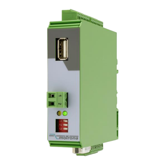
Page 10: Connections And Control Elements
4. Connections and Control Elements For electrical connection the unit provides four plug-in terminal strips X and X , with mechanical codification against accidental misconnection. The 9-position Sub-D-connector X and the front USB port provide communication and PC setup of the unit. 4.1. -
Page 11: Control Inputs Control1 - Control4
4.2. Control Inputs Control1 - Control4 Four control inputs with programmable function are accessible via terminals X . The 7, 8] desired function can be assigned by the parameters [Input Config.] and [Input Function] of the „Command Setting“ menu. All control inputs are designed as PNP inputs, i.e. a positive voltage must be applied with reference to GND. -
Page 12: Analogue Inputs
4.4. Analogue Inputs The differential inputs on the input side of the converter accept standard voltages (± 10 V), standard currents (0/4 - 20 mA) and also potentiometer connection. The drawings below explain the principle of the input circuits with each of the input connection modes. Voltage input Current input Potentiometer-input... -
Page 13: The Serial Interface
4.6. The Serial Interface Both, a serial RS 232 interface and a RS 485 interface are available on the unit; however the converter can only communicate by one or by the other interface, but not by both at a time. Serial communication allows readout of internal measuring and conversion results and is also required for setup and commissioning of the unit.via PC. -
Page 14: The Usb Communication Port
For connection of the converter to a PC via USB a connection cable with “type A” connectors on both sides is required (A-A-cable, available in Electronic Shops or from motrona). Special hints for operation of the USB port can be found in chapter 7. -
Page 15: Parameter Settings
5. Parameter Settings For setting of parameters and commissioning a PC with Operator Software OS32 is required. Please connect your PC to the unit via USB cable (see and 7) or by serial link (see 4.6). After starting the OS32 software the following screen will appear: Where you find the parameter field empty with the top line indicating “OFFLINE”, please click to the “Comms”... -
Page 16: General Settings
5.1. General Settings Parameter Description Range Default Ser. Operational Mode: 0, 1, 2, 3 0: Analogue input => Frequency (incremental output) 1: Analogue input => Position (incremental output) 2: Analogue input => Position (incremental output) 3: Analogue input => Position (SSI interface) Special Mode: 0, 1, 2 0: standard operation as a signal converter... -
Page 17: Analogue Settings (Analogue Input)
5.2. Analogue Settings (Analogue Input) Parameter Description Range Default Ser. Analogue Mode: Input characteristics 0, 1 0: Input signal = voltage (±10 V) 1: Input signal = current (0/4 - 20 mA) Analogue Low Value: Beginning of the analogue range ±... -
Page 18: Encoder Setting (Incremental Output)
5.4. Encoder Setting (Incremental Output) Parameter Description Range Default Ser. POS Low Value: Beginning of the position count where ±100 000 000 the analogue input equals to „Analogue Low Value“ (increments) POS High Value: End of the position count where ±100 000 000 10 000 the analogue input equals to „Analogue High Value“... -
Page 19: Serial Setting (Rs232/Rs485 Interface)
5.6. Serial Setting (RS232/RS485 Interface) Parameter Description Range Default Ser. Unit Number (serial device address) 11 … 99 Serial Baud Rate (communication speed) 0 - 10 9600 Bauds 4800 Bauds 2400 Bauds 1200 Bauds 600 Bauds 19 200 Bauds 38 400 Bauds 56 000 Bauds 57 600 Bauds 76 800 Bauds... -
Page 20: Linearization Setting
5.7. Linearization Setting Linearization Table Range Default Ser. First interpolation point (x0, original value) First interpolation point (y0 as substitution for x0) … Second interpolation point (x1, original value) -10 000 … +10 000 … Second interpolation point (y1 as substitution for x1) …... -
Page 21: Hints For Serial Communication
6. Hints for Serial Communication Serial communication with the UZ210 converter is intended to be used for Setup and programming of the unit by PC with operator software OS32 (see chapter 5) Automatic and cyclic transmission of converter data to a PC or PLC or data logger ... -
Page 22: Communication Protocol
6.2. Communication Protocol When communicating with the unit via protocol, you have full read/write access to all internal parameters, states and actual values. The protocol uses the DRIVECOM standard according to DIN ISO 1745. The serial access codes of all parameters can be found in the parameter description (see chapter 5). - Page 23 To write parameter data to the unit the following data string must be sent: EOT AD1 AD2 STX C1 C2 x x x x x x x ETX BCC EOT = control character (Hex 04) AD1 = unit address, High Byte AD2 = unit address, Low Byte STX = control character (Hex 02) C1 = register code to write data, High Byte...
-
Page 24: Hints For Operation Of The Usb Port
Prior to using the USB port it is mandatory to store the driver file „motrona_vcom.inf“ in a user- defined directory of the PC (any directory according to your own choice will be fine). The driver file is available for download from the SUPPORT section of the motrona website www.motrona.com. - Page 25 Uz210_02c_oi_e.doc / Dez-15 Page 25 / 27...
-
Page 26: Technical Specifications
600, 1200, 2400, 9600 (Default), 19200, 38400, 56000, 57600, 76800 and 115200 Connections: SUB-D connector (female), 9-pin USB interface: Version: USB 2.0 Driver: motrona_vcom.inf (download on www.motrona.com) Connections: by USB-Port, connector type „A Uz210_02c_oi_e.doc / Dez-15 Page 26 / 27... -
Page 27: Dimensions
Continuation “Technical Specifications” Housing: Material: plastic Mounting: 35 mm top hat rail (according to EN 60715) Dimensions (w x h x d): 22.5 x 102 x 102 mm Protection class: IP20 Weight: approx. 100 g Temperature range: Operation: 0 °C … +45 °C / +32 … +113 °F (not condensing) Storage: -25 °C …...
Need help?
Do you have a question about the UZ210 and is the answer not in the manual?
Questions and answers