Table of Contents
Advertisement
Quick Links
control
– motion – interface
Adjustable Multiplication Rate,
for Use with Sine/Cosine Encoder Systems
• Converts sinus wave inputs with 1 Vss standard level into incremental quadrature
output signals
• Outputs A, /A, B, /B, Z, /Z (RS422 / TTL) and A, B, Z (80 – 30 V HTL)
• Adjustable multiplier for interpolation rates from 1:5 to 1:50
• Adjustable divider 1:1 – 1:128 to reduce the output frequency
• Sinus-input frequency 0 - 400 kHz
• Quadrature output frequency up to 4 MHz
• Adjustable glitch filter
• Power supply 18 – 30 VDC
SI25101B_e.DOC / Mrz-08
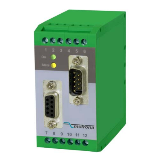
SI 251
Sine/Cosine Interpolator with
Operating Instructions
ELEKTRO-TRADING sp. z o.o
Tel.
+48 (0-32) 734-55-72
Tel/Fax +48 (0-32) 734-55-70
E-Mail et@elektro-trading.com.pl
http://www.elektro-trading.com.pl
Page 1 / 16
Advertisement
Table of Contents

Subscribe to Our Youtube Channel
Related Manuals for Motrona SI 251


Summary of Contents for Motrona SI 251
- Page 1 Tel/Fax +48 (0-32) 734-55-70 E-Mail et@elektro-trading.com.pl http://www.elektro-trading.com.pl control – motion – interface SI 251 Sine/Cosine Interpolator with Adjustable Multiplication Rate, for Use with Sine/Cosine Encoder Systems • Converts sinus wave inputs with 1 Vss standard level into incremental quadrature output signals •...
- Page 2 Safety Instructions • This manual is an essential part of the unit and contains important hints about function, correct handling and commissioning. Non-observance can result in damage to the unit or the machine or even in injury to persons using the equipment! •...
-
Page 3: Table Of Contents
Table of Contents 1. Introduction....................4 2. Block Diagram ....................5 3. Connections ....................6 4. Pin assignment of SUB-D-connectors ............8 4.1. Sine/Cosine inputs ....................8 4.2. RS 422 impulse output ..................9 5. Switch settings .................... 10 6. Frequency Divider and Error Signals ............13 7. -
Page 4: Introduction
1. Introduction SI251 represents an encoder interface unit, designed to convert output signals of so-called “sine-cosine-encoders” and similar measuring systems into incremental quadrature impulse signals. Under consideration of an adjustable multiplier the unit interpolates a corresponding number of impulses from every sine wave. An additional programmable divider provides division of the impulses if applicable, before they appear at the output. -
Page 5: Block Diagram
2. Block Diagram Vdd = 20 V / 150 mA Vcc = 5.2V / 150 mA Encoder Supply Power /A ,/B, /Z, A, B, Z SIN+ SIN- COS+ COS- REF+ REF- SI25101B_e.DOC / Mrz-08 Page 5 / 16... -
Page 6: Connections
3. Connections The unit provides a 9-pin Sub-D connector (female on the unit site) for connection of the sine/cosine sensor. For easy power supply of the encoder, an external jumper allows to switch an auxiliary voltage of either 5.2 volts or approx. 20 volts to the same connector. Also the mean voltage is available on the connector pins, allowing also the use of sensors with non- differential sinus output. - Page 7 Pushbutton and DIL switch 2 (Configuration) Encoder supply LED’s DIL-switch 1 iImpulse divider) At any time, the over-all transmission characteristics of encoder, external components and capacity of cable must ensure proper signals at the input of the unit, with respect to levels, shape and phase displacement A/B.
-
Page 8: Pin Assignment Of Sub-D-Connectors
4. Pin assignment of SUB-D-connectors 4.1. Sine/Cosine inputs Standard encoders with differential outputs can be connected directly to the corresponding pins SIN+, SIN-, COS+, COS-, REF+, REF-. Where longer cables must be used, terminating resistors between the non-inverted and the inverted signal of each channel may be of advantage. -
Page 9: Rs 422 Impulse Output
When the reference signals REF+ and REF- are not used or not available, the related inputs of the converter must be tied to a defined potential. When you connect the REF- pin to V with the REF+ pin open, the unit will generate a Z impulse with every sine period. -
Page 10: Switch Settings
5. Switch settings Switch DIL1 allows to set the filter and to choose the interpolation rate and interpolation time. Switch DIL2 selects a programmable divider and allows to set the unit to test mode Changes of the DIL switch positions will become active only after the next power-up of the unit! DIL1: ( 0 = OFF, 1 = ON ) Interpolation and Filtering... - Page 11 Hints for settings of DIL switch 1: • Under proper electrical conditions there is no imperative need to use the filtering functions offered in the table above. When you set your interpolation factor with use of the filter settings highlighted in the table, there will be no further restrictions with the operating range of the unit.
- Page 12 Maximum output Maximum input Interpolation rate Interpolation time frequency frequency 25 ns 4 MHz 320 kHz 100 ns 2.5 MHz 200 kHz x12,5 400 ns 625 kHz 50 kHz 1600 ns 156.25 kHz 12.5 kHz 25 ns 4 MHz 200 kHz 100 ns 2.5 MHz 125 kHz...
-
Page 13: Frequency Divider And Error Signals
6. Frequency Divider and Error Signals The programmable frequency divider provides decrease of the output frequency by an adjustable division rate between 1:1 and 1: 128. The following errors are detected and indicated by the yellow LED and the Error output: •... -
Page 14: Delays
Where unrulable potential situations should come up, it is recommended to use a fully separate power supply for the SI 251 unit SI25101B_e.DOC / Mrz-08 Page 14 / 16... -
Page 15: Dimensions
9. Dimensions 91mm (3.583’’) 40 mm (1.575’’) 74 mm (2.193’’) Front view Side view SI25101B_e.DOC / Mrz-08 Page 15 / 16... -
Page 16: Technical Data
10. Technical Data Power Supply (with no external load) Vdd = 18 V DC (0.15 A) – 30 V DC (0.09 A) Aux. Voltage Output 1 5.2 V / max. 150 mA Aux. Voltage Output 2 Vdd – 4V / max. 150 mA Input frequency max.
Need help?
Do you have a question about the SI 251 and is the answer not in the manual?
Questions and answers