Table of Contents
Advertisement
Quick Links
control – motion –
Input:
sin / cos 1 Vpp
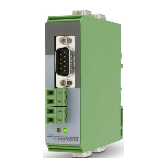
SV 211
Encoder inputs sin+, sin-, cos+, cos-, ref+, ref- with 1 Vpp format
Four sine-cosine output channels with the same signal format
Suitable for input frequencies up to 500 kHz
Power supply 17 - 30 VDC (potential separated) and auxiliary output 5V
SV21101b_e.doc / Feb-13
interface
SV 211
Signal Splitter for
Sine-Cosine Encoders
Operating Instructions
Out 1
sin / cos 1Vpp
Out 2
sin / cos 1Vpp
Out 3
sin / cos 1Vpp
Out 4
sin / cos 1Vpp
motrona GmbH
Zwischen den Wegen 32
78239 Rielasingen - Germany
Tel. +49 (0)7731-9332-0
Fax +49 (0)7731-9332-30
info@motrona.com
www.motrona.de
Page 1 / 8
Advertisement
Table of Contents

Subscribe to Our Youtube Channel
Related Manuals for Motrona SV 211


Summary of Contents for Motrona SV 211
- Page 1 Zwischen den Wegen 32 78239 Rielasingen - Germany Tel. +49 (0)7731-9332-0 Fax +49 (0)7731-9332-30 control – motion – interface info@motrona.com www.motrona.de SV 211 Signal Splitter for Sine-Cosine Encoders Out 1 sin / cos 1Vpp Input: sin / cos 1 Vpp Out 2...
- Page 2 - Errors and omissions excepted – General instructions for cabling, screening and grounding can be found in the SUPPORT section of our website http://www.motrona.com Version: Description: SV21101a_Jan. 2013/af/nw First edition SV21101a_Feb.
- Page 3 Table of Contents 1. Application ....................4 2. Connection Diagram ..................5 2.1. Power and Encoder Supply (X6/X7)................5 2.2. Connection of the Sine-Cosine Encoder (X5) ............6 2.3. The Sine-Cosine Outputs (X1, X2, X3 und X4)............6 3. The Front LEDs..................... 7 4.
- Page 4 1. Application The SV 211 encoder splitter has been designed for clean and trouble-free distribution of the output signals of sine-cosine type encoders to several target units. On all sine output channels the same signal format is available as on the input site, including a reference impulse (if available on the input site).
- Page 5 2. Connection Diagram For wiring of the sinusoidal signals the unit provides 5 Sub-D-9 connectors (X1, X2, X3, X4 and X5). For all other connections 2 screw terminal strips are available (X6 and X7). All Sub-D 9 connector housings are connected with the GND potential. Output 1 Output 2 (sin-cos 1 Vpp)
- Page 6 2.2. Connection of the Sine-Cosine Encoder (X5) The encoder can be connected via the front Sub-D-9 connector marked X5 (male connector on unit side, female connector on the encoder cable). Only encoders with differential sine-cosine signals of 1 Vpp can be used (0.8 Vpp - 1.2 Vpp). At any time the signals sin+/sin- and cos+/cos- must be available.
- Page 7 It is recommendable to connect the cable shield directly to the metal housing of the associated counterpart connector. This ensures that the cable is connected with the GND potential in any case via SV211. 3. The Front LEDs The green LED is lit whenever the power supply of the unit is on. The yellow LED indicates the availability of the encoder supply +5V.
- Page 8 5. Technical Specifications Power supply Vin 17 V - 30 VDC Supply current approx. 50 mA (unloaded) Aux. encoder power output 5,2V / 150 mA (or according to remote feed-in) Max. frequency 500 kHz Signal inputs 6 symmetric differential sin/cos - inputs (Terminating resistors 3 x 120 ohms inbuilt) (sin+, sin-, cos+, cos-, ref+, ref-), Signal level 0,8 Vpp - 1,2 Vpp,...
Need help?
Do you have a question about the SV 211 and is the answer not in the manual?
Questions and answers