Table of Contents
Advertisement
Quick Links
Operating Manual
Incremental encoder simulator to simulate the function of incremental encoders & scales
Product Features:
Output frequency adjustable from 50 to 500 kHz
Indexing function to generate impulse chains with a counted number of impulses
Outputs A, /A, B, /B, Z, /Z with 5 V-TTL or HTL level (10 to 30 VDC)
Adjustable direction of rotation (phase relation A / B)
Programmable marker pulse distance
5 to 30 VDC power supply
motrona GmbH, Zeppelinstraße 16, DE - 78244 Gottmadingen, Tel. +49 (0) 7731 9332-0, Fax +49 (0) 7731 9332-30, info@motrona.com, www.motrona.com
ES001
Advertisement
Table of Contents

Subscribe to Our Youtube Channel
Related Manuals for Motrona ES001


Summary of Contents for Motrona ES001
- Page 1 Adjustable direction of rotation (phase relation A / B) Programmable marker pulse distance 5 to 30 VDC power supply motrona GmbH, Zeppelinstraße 16, DE - 78244 Gottmadingen, Tel. +49 (0) 7731 9332-0, Fax +49 (0) 7731 9332-30, info@motrona.com, www.motrona.com...
-
Page 2: Table Of Contents
Minor corrections and “Legal notices” supplemented. Legal notices: All contents included in this manual are protected by the terms of use and copyrights of motrona GmbH. Any reproduction, modification, usage or publication in other electronic and printed media as well as in the internet requires prior written authorization by motrona GmbH. -
Page 3: Safety Instructions And Responsibility
1. Safety Instructions and Responsibility 1.1 General Safety Instructions This operation manual is a significant component of the unit and includes important rules and hints about the installation, function and usage. Non-observance can result in damage and/or impairment of the functions to the unit or the machine or even in injury to persons using the equipment! Please read the following instructions carefully before operating the device and observe all safety and warning instructions! Keep the manual for later use. -
Page 4: Installation
For placement, wiring, environmental conditions as well as shielding and earthing/grounding of the supply lines the general standards of industrial automation industry and the specific shielding instructions of the manufacturer are valid. Please find all respective hints and rules on www.motrona.com/download.html --> “[General EMC Rules for Wiring, Screening and Earthing]”. -
Page 5: Introduction
Localization of error sources with malfunction and trouble-shooting ES001 provides simulation of a wide speed range, from single step and slow motion up to encoder frequencies of 500 kHz. The unit is suitable to generate TTL and HTL level impulses with forward or reverse rotation, including a programmable zero pulse. -
Page 6: Connections
Pin assignment: For technical reasons, the pin assignment of the ES001 encoder simulator diverges from the usual motrona standard pin assignments. -
Page 7: Connection To Other Motrona Units
3.2 Connection to other motrona units Due to different pin assignments, the two ends of a cable with Sub-D-connectors are not interconvertible. To avoid misconnection, we recommend to either code the two connectors, or to at least mark the cable ends clearly. -
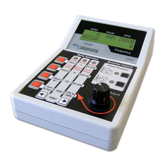
Page 8: Display Panel And Control Panel
4. Display and Control Panels 4.1 Display Panel The display panel is grouped into the following 5 sections: Section Description Setting Range Display Range 0 …15000 Actual speed (rev./min) (= 60 * Frequency/ PPR) (with overflow) Mode Actual operating mode PPR, MAN, RATE Preset number of pulses per rev. -
Page 9: Control Panel
4.2 Control Panel The control panel is grouped into the sections Mode-Selection, Direction Control and Hertz Fine Adjust Direction Preset Selection Keys Frequency Fine Adjust Mode Selection (PPR, MAN, RATE) 4.3 Operating Modes PPR, MAN and RATE The desired operating mode can be selected by means of the two Mode Select Keys. The red LED at the top of each column shows the selected function (PPR, MAN or RATE). -
Page 10: The Man Mode
4.3.2 The MAN Mode This mode provides the facility to manually control the number of output signals sent. Each operation of one of the red keys sends the number of output pulses indicated on the middle column of the control panel (1, 10, 100 or 1000 pulses). The associated output frequency can beforehand be selected in the “Rate”... -
Page 11: Technical Specifications
5. Technical Specifications Power supply: Input voltage: 5 … 30 VDC Protection circuit reverse polarity protection Ripple: ≤ 10 % at 24 VDC Consumption: approx. 100 mA Connections: Connector type: SUB-D connector (male), 9-pin Incremental output: Signal levels: 5 V-TTL or 10 … 30 V HTL (according to the power supply voltage).
Need help?
Do you have a question about the ES001 and is the answer not in the manual?
Questions and answers