Table of Contents
Advertisement
Quick Links
Operating Manual
Product features:
Programmable encoder input A, /A, B, /B, Z, /Z, for use with RS422 or
TTL differential signals or with HTL signals (differential or single-ended)
Two encoder outputs (A, /A, B, /B, Z, /Z each) with individually programmable
output levels (TTL 5 V or HTL 10 to 30 V)
Max. frequency 750 kHz (TTL) or 300 kHz (HTL)
Power supply either 5 VDC or 10 to 30 VDC
Aux. voltage output +5 V for encoder supply
(with 10 to 30 VDC power supply)
motrona GmbH, Zeppelinstraße 16, DE - 78244 Gottmadingen, Tel. +49 (0) 7731 9332-0, Fax +49 (0) 7731 9332-30, info@motrona.com, www.motrona.com
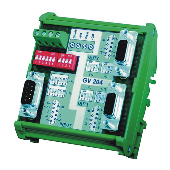
GV204
Impulse Splitter for Incremental Encoders
Advertisement
Table of Contents

Subscribe to Our Youtube Channel
Related Manuals for Motrona GV204


Summary of Contents for Motrona GV204
- Page 1 Power supply either 5 VDC or 10 to 30 VDC Aux. voltage output +5 V for encoder supply (with 10 to 30 VDC power supply) motrona GmbH, Zeppelinstraße 16, DE - 78244 Gottmadingen, Tel. +49 (0) 7731 9332-0, Fax +49 (0) 7731 9332-30, info@motrona.com, www.motrona.com...
-
Page 2: Table Of Contents
„Impulse Outputs“. Legal notices: All contents included in this manual are protected by the terms of use and copyrights of motrona GmbH. Any reproduction, modification, usage or publication in other electronic and printed media as well as in the internet requires prior written authorization by motrona GmbH. -
Page 3: Safety Instructions And Responsibility
1. Safety Instructions and Responsibility 1.1. General Safety Instructions This operation manual is a significant component of the unit and includes important rules and hints about the installation, function and usage. Non-observance can result in damage and/or impairment of the functions to the unit or the machine or even in injury to persons using the equipment! Please read the following instructions carefully before operating the device and observe all safety and warning instructions! Keep the manual for later use. -
Page 4: Installation
1.3. Installation The device is only allowed to be installed and operated within the permissible temperature range. Please ensure an adequate ventilation and avoid all direct contact between the device and hot or aggressive gases and liquids. Before installation or maintenance, the unit must be disconnected from all voltage-sources. Further it must be ensured that no danger can arise by touching the disconnected voltage- sources. -
Page 5: Cleaning, Maintenance And Service Notes
Please find all respective hints and rules on www.motrona.com/download.html --> “[General EMC Rules for Wiring, Screening and Earthing]”. 1.4. Cleaning, Maintenance and Service Notes To clean the front of the unit please use only a slightly damp (not wet!), soft cloth. -
Page 6: Compatibility Hint
GV203 (dual splitter with HTL input) The new GV204 model is fully compatible to the previous models with all functions, connections, dimensions and technical specifications. Merely the successor model provides an additional DIL switch to set the input format to either TTL or HTL level, which allows to replace both parent models by just one new model. -
Page 7: Block Diagram
4. Block Diagram The subsequent block diagram shows all essential circuit details of a GV204 unit: Shield +V Output 2 OUT1 (Sub-D-9 female) +5,4V Vext IN HTL Vout +5,4V OUT2 Output 1 (Sub-D-9 female) Vext Input (Sub-D-9 male) Gv204_01c_oi_e.doc / Apr-16... -
Page 8: Power Supply
5. Power Supply 5.1. Supply via +V from an unstabilized 10 ... 30 VDC source In general, the unit is supplied with an unstabilized DC voltage of 10 ... 30 VDC, using the screw terminals +V and GND. In this case pin 4 of the input SUB-D-connector will also provide a +5 V auxiliary output for encoder supply (max. -
Page 9: Impulse Inputs
(no inverted signals required) Other switch positions than shown above are reserved for special applications and must only be used upon advice of motrona. *) Where for encoder supply a voltage higher than 5.4 V should be required, please apply an... -
Page 10: Impulse Outputs And Output Levels
7. Impulse Outputs and Output Levels The output signals are available on the two SUB-D-connectors marked "OUT1" and OUT2" (female connectors on unit site). The pin assignment is shown in the block diagram and is also printed to the top side of the unit. The four-position DIL-Switch provides individual setting of the output levels for each of the two output channels. -
Page 11: Dimensions
8. Dimensions 2 3 4 5 6 12 3 4 (3.543’’) 85 (3.346’’) (1.496’’) (1.969’’) Gv204_01c_oi_e.doc / Apr-16 Page 11 / 12... -
Page 12: Technical Specifications
9. Technical Specifications Power supply: Input voltage 5 … 30 VDC (at pin Vext) or (selective): 10 … 30 VDC (at pin VB) Protection circuit: reverse polarity protection Ripple: ≤ 10 % at 24 VDC Consumption: approx. 5… 50 mA, unloaded (depends on input voltage) Connections: screw terminal, 1.5 mm²...
Need help?
Do you have a question about the GV204 and is the answer not in the manual?
Questions and answers