Table of Contents
Advertisement
Quick Links
Operating Manual
Product features:
•
Adjustable Multiplier / divider (F1/F2)
•
Input format RS-422, HTL single ended, HTL differential or TTL
•
Multiplication / division without cumulative residual error
•
Additional functions like Jog, Trim, Offset and Reference
•
Input frequency up to 1MHz, depending on input format
•
Output frequency max. 1MHz
•
Two HTL outputs to display different states
•
Supply 9 to 30 VDC
motrona GmbH, Zeppelinstraße 16, DE - 78244 Gottmadingen, Tel. +49 (0) 7731 9332-0, Fax +49 (0) 7731 9332-30, info@motrona.com, www.motrona.com
FM210
Frequency Multiplier, Frequency Divider
Advertisement
Table of Contents

Subscribe to Our Youtube Channel
Related Manuals for Motrona FM210


Summary of Contents for Motrona FM210
- Page 1 Input frequency up to 1MHz, depending on input format • Output frequency max. 1MHz • Two HTL outputs to display different states • Supply 9 to 30 VDC motrona GmbH, Zeppelinstraße 16, DE - 78244 Gottmadingen, Tel. +49 (0) 7731 9332-0, Fax +49 (0) 7731 9332-30, info@motrona.com, www.motrona.com...
- Page 2 Version 1 Disclaimer: All contents included in this manual are protected by the terms of use and copyrights of motrona GmbH. Any reproduction, modification, usage or publication in other electronic and printed media as well as in the internet requires prior written authorization by motrona GmbH.
-
Page 3: Table Of Contents
Table of Contents Safety Instructions and Responsibility ..............5 General Safety Instructions......................5 Use according to the intended purpose ..................5 Installation ..........................6 EMC Guidelines ......................... 7 Cleaning, Maintenance and Service Notes ................7 Introduction ........................ 8 Block Diagram ......................8 Electrical Connections .................... - Page 4 Output Functions...................... 28 Encoder Error .......................... 28 Phase Error ..........................28 Direction (f > 0) ........................28 Condition Reset Static ......................28 Command Process Reference ....................28 Command Process Jog ......................28 Lecom Protocol ......................29 Lecom Read ..........................29 Lecom Write..........................
-
Page 5: Safety Instructions And Responsibility
Safety Instructions and Responsibility General Safety Instructions This operation manual is a significant component of the unit and includes important rules and hints about the installation, function and usage. Non-observance can result in damage and/or impairment of the functions to the unit or the machine or even in injury to persons using the equipment! Please read the following instructions carefully before operating the unit and observe all safety and warning instructions! Keep the manual for later use. -
Page 6: Installation
Installation The unit is only allowed to be installed and operated within the permissible temperature range. Please ensure an adequate ventilation and avoid all direct contact between the unit and hot or aggressive gases and liquids. Before installation or maintenance, the unit must be disconnected from all voltage-sources. Further it must be ensured that no danger can arise by touching the disconnected voltage-sources. -
Page 7: Emc Guidelines
Run signal and control cables apart from power lines and other cables emitting electromagnetic • noise. Please also refer to motrona manual “General Rules for Cabling, Grounding, Cabinet Assembly”. You can download that manual by the link https://www.motrona.com/en/support/general-certificates.html Cleaning, Maintenance and Service Notes To clean the front of the unit please use only a slightly damp (not wet!), soft cloth. -
Page 8: Introduction
Introduction The FM210 is an intelligent unit for proportional conversion of an input frequency fin into an output frequency fout. The ratio results from setting two variable factors F1 (Parameter Factor 1) and F2 (Parameter Factor 2). Applications are mainly in the field of digital, frequency-controlled drives in the realization of electronic shafts or electronically adjustable gears. -
Page 9: Electrical Connections
Electrical Connections The clamps should be tightened with a slotted screwdriver (blade width 2mm). Please note that all inputs and outputs refer to the same ground potential GND (except USB), which is also the negative pole of the unit supply. In any case, it must be ensured that the signal quality of the entire arrangement including the encoder, any external circuitry and cable capacitance ensure a perfect pulse pattern at the unit input (pulse level,... -
Page 10: Encoder Inputs A, /A, B, /B, Z, /Z
Encoder Inputs A, /A, B, /B, Z, /Z An encoder input A/B 90° for HTL/TTL/RS-422 signals is available at terminals 2 - 7 of X4. The unused inputs must either remain open (HTL Single Ended as opposed to HTL Differential), or possibly be terminated (unused Z-lines in RS-422 or HTL Differential Format). -
Page 11: Control-Inputs Inx
Control-Inputs INx 4 control inputs with HTL PNP characteristics are available on terminal 2 – 5 of X3. Open control inputs are “low active”. The inputs could be used for control purposes. They could be used for different functions regarding the parameterization. Encoder Output A, /A, B, /B, Z, /Z At the outputs of terminal X6, the encoder signals are available either in HTL or RS-422 format, depending on the DIL switch S2/1 setting. -
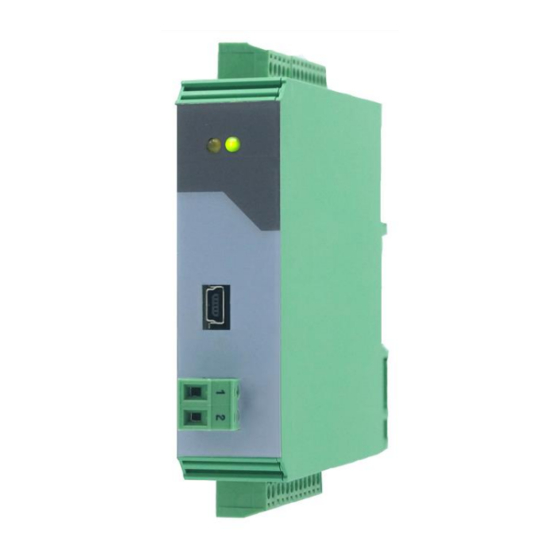
Page 12: Leds
LEDs The green LED shows that the unit is ready (power supply switched on). The yellow LED shows an input error in case of a static illumination. (only with RS-422 or HTL differential), otherwise it flashes. DIL Switch The DIL switch S1 is used to detect an input error with HTL differential or RS-422 format. The A line can be monitored via DIL1/1. -
Page 13: Parameter
Parameter Factor Menu Nr. Parameter Adjustment range Default 000 Factor 1: 0,0001 - 9,9999 1,0000 Proportional factor of the pulse ratio. f out = (F1 x f in) / F2 001 Factor 2: 0,0001 - 9,9999 1,0000 Reciprocal factor of the pulse ratio. f out = (F1 x f in) / F2 002 Reserved Command Menu... -
Page 14: General Menu
General Menu Nr. Parameter Adjustment range Default 013 Encoder Mode: 0 – 4 This parameter sets the input format of the encoder. 0 : Differential HTL 1 : RS-422 2 : HTL1 (Low 0…5V, High 9…30 V) 3 : HTL2 (Low 0…10V, High 14…30 V) 4 : TTL 014 Z Pulse: 0 –... -
Page 15: Input Menu
Input Menu Nr. Parameter Adjustment range Default 025 Input 1 Config: 0 - 1 Defines the input behavior 0: Static Low, Function triggering at a "low" state 1: Static High, Function triggering at a "high" state 026 Input 1 Function: 0 - 12 0: No Function 1: Reset Edge... -
Page 16: Output Menu
Output Menu Nr. Parameter Adjustment range Default 033 Output 1 Function: 0 - 7 0: No function 1: Encoder input error (only with input format RS-422 or HTL differential) 2: Phase error (parameter Diff Error exceeded) 3: Fout > 0 (Direction recognition) 4: Reset activated 5: Reference activated 6: Jog activated... -
Page 17: Serial Menu
Serial Menu Nr. Parameter Adjustment range Default 042 USB Unit No.: USB unit number for the virtual port is fixed to 11. 043 USB Baud Rate: USB baud rate for the virtual port is fixed at 115.2 kBaud. 044 USB Baud Rate: USB format for the virtual port is fixed to 8N1. -
Page 18: Commissioning
Commissioning Setting the Encoder Mode First the parameter Encoder Mode must be selected for the connected encoder. For connection or wiring see chapter Encoder Inputs. Depending on the selection of the encoder mode, an input error can be detected on the input lines A, /A, B, /B or Z, /Z. (short circuit or possible line break depending on termination). -
Page 19: Additional Optional Settings
Additional Optional Settings 6.5.1. Setting the Z Output Pulses The number of the Z output signals can be defined by the parameter Z Pulse. The Z output is set in the high phase of the A and B signal. The Z output pulses can be referenced by an input or by a command with the input Z pulses. As long as the input or command is active, the internal Z counter is reset with every Z pulse and thus referenced. -
Page 20: Input Functions
Input Functions Reset Static The Reset Static function sets the frequency output to 0Hz independent of the frequency input. This function also resets the commands for Reference and Jog. Triggering Parameter Comment Addition Input Input X Config = 0/1 If Input X Config = 0 is set, the command is The status of the input can be Input X Function = 11 triggered in case of a "low"... -
Page 21: Trim
Trim+/- The Trim+/- function continuously adds or subtracts increments into the differential counter and thus ensures that the output runs away, for example for a position shifting to the master drive. The time per added or subtracted pulse is indicated by the Trim Speed parameter. A setting of zero executes this in minimum time (loop time). -
Page 22: Offset Edge
Offset Edge The Offset Edge function adds or subtracts once with the falling command edge increments into the differential counter and thus ensures that the output runs away, for example for a position shifting to the master drive. The Offset parameter is used to indicate the number of added or subtracted pulses. This command is similar to the Trim command. -
Page 23: Z Reference
Z Reference The Z Reference function references the Z Pulse input to the output. If the command is activated, a Z Pulse at the input resets the internal Z counter. This allows the output Z Pulse to be brought into a certain position to the input. - Page 24 If the jog command is reset within the rising time of the ramp, the frequency is changed from the current point and falls to zero. If a new jog command is set during the downward ramp, a jump to zero is executed and then the new rising ramp is started.
-
Page 25: Prestop Mark
Process Jog: New setting of Jog before 0Hz are reached (Special Mode = 0) Process Jog: New setting of Jog before 0Hz are reached (Special Mode not equal to zero) Prestop Mark The Prestop Mark function corresponds to the pre-stop signal. This command is used with Reference and Prestop Edge. -
Page 26: Edge Prestop
Edge Prestop The Edge Prestop function corresponds to the edge of the pre-stop signal. This command is used with Reference and Prestop Mark. Triggering Parameter Comment Addition Input Input X Config = 0/1 If Input X Config = 0 is set, the command is The status of the input can be Input X Function = 10 triggered in case of a "low"... - Page 27 Note: The parameter Ref Speed High must always be larger than Ref Speed Low. If the parameter Ref Ramp is set to zero, a jump is executed. A negative ramp end point can be achieved with the Direction command. The Direction command should be executed before the Reference command is set.
-
Page 28: Output Functions
Output Functions All output functions can be inverted by the Output Polarity parameter. Encoder Error If RS-422 or HTL differential is selected as encoder mode, an input error can be detected with the DIL switch. This error can then be shown via an output. The output field of the OS can also be used to display this error (Enc. -
Page 29: Lecom Protocol
Lecom Protocol If you communicate with the unit by the Lecom protocol, you have full read and write access to all internal parameters, states and actual values. The unit uses the Lecom protocol according to DIN ISO 1745. The serial access codes for all parameters of the unit are specified in the parameter list. -
Page 30: Lecom Write
Lecom Write To write data to the unit the following string must be sent: EOT AD1 AD2 STX C1 C2 x x x x x x x ETX BCC EOT = control character (Hex 04) AD1 = unit address, High Byte AD2 = unit address, Low Byte STX = control character (Hex 02) C1 = code, High Byte... -
Page 31: Modbus Protocol
Attention: The Modbus checksum sequence L/H is just reversed to the data. The FM210 supports the function Reading Holding Register (R, FCT = 03), the function Report Slave ID (R, FCT = 11) and the function Preset Single Register (W, FCT = 06). -
Page 32: Modbus Write
The unit will answer if the request is correct: ADR FCT CB DATA CRCL CRCH ADR = MB address (Parameter) FCT = function (Hex 03) CB = number of bytes, here 4 bytes DATA = data, 4 bytes (32 Bit) CRCx = checksum CRC16 Designation: DATA... - Page 33 The unit will answer if the request is correct: ADR FCT REG DATA CRCL CRCH ADR = MB address (parameter) FCT = function (Hex 06) REG = register address DATA = data CRCx = checksum CRC16 Designation: DATA CRCL CRCH Hexadecimal: 00 0E 00 01...
- Page 34 46 4D 32 31 30 30 31 42 corresponds in ASCII format: FM21001B Here the unit header, which is also visible in the OS, is displayed. It identifies the unit (FM210) with software version (01B) and, if available, the special number. Splitting of the memory area...
-
Page 35: Modbus Crc Calculation
Modbus CRC Calculation The Modbus CRC Reset parameter is used to reset the CRC Calulator. If Modbus CRC Reset = 0, the CRC Calculator is set to FFFF in the monitor field (Page 1; Variable <4). If Modbus CRC Reset = 1, the CRC value can be calculated with every Modbus byte. -
Page 36: Overshoot
To obtain an optimal correction over a wide frequency range, the Base Correction value must first be set at low frequency (approx. 10 kHz). Here the other two parameters (Correction Freq and Correction Value) are set to zero. Now start with values at 25 and check the deviation of the differential counter. -
Page 37: Parameter List
Parameter List Min – Max – Decimal Lecom Modbus Parameter Default Places value value places Code Code L00/H02 000 Factor 1 99999 10000 L04/H06 001 Factor 2 99999 10000 L08/H0A 002 Reserved 10000 1000 L0C/H0E 003 Ref. Speed High 1000000 4000 L10/H12 004 Ref. - Page 38 Min – Max – Decimal Lecom Modbus Parameter Default Places value value places Code Code L98/H9A 038 Modbus Address L9C/H9E 039 Modbus CRC Reset LA0/HA2 040 Modbus CRC Byte LA4/HA6 041 Reserved 10000 1000 LA8/HAA 042 USB Unit Nr. LAC/HAE 043 USB Baud Rate LB0/HB2 044 USB Format...
-
Page 39: Dimensions
Dimensions Fm210_01b_oi_e.docx / Nov-20 Page 39 / 40... -
Page 40: Technical Specifications
Technical Specifications Technical specifications: Connections: Connector type: screw terminal, 1,5 mm² / AWG 16 Power supply: Input voltage: 9 … 30 VDC Protection circuit: reverse polarity protection Ripple: ≤ 10 % Consumption: approx. 70 mA (at 9 V unloaded) approx. 47 mA (at 30 V, unloaded) Encoder supply: Output voltage: 5,5 VDC...
Need help?
Do you have a question about the FM210 and is the answer not in the manual?
Questions and answers