
Subscribe to Our Youtube Channel
Related Manuals for E+E Elektronik EE771 Series


Summary of Contents for E+E Elektronik EE771 Series
- Page 1 EE771 Series FLOW METER for COMPRESSED AIR and GASES Manual Hardware and Software BA_EE771_e // V4.1 // technical data are subject to change // 193296...
- Page 2 The content will be revised on a regular basis. These changes will be implemented in later versions. The described products can be improved and changed at any time without prior notice. © Copyright E+E Elektronik Ges.m.b.H. ® All rights reserved.
-
Page 3: Table Of Contents
Table of contents - HARDWARE ......................1. GENERAL ....................1.1. Safety Instructions ....................1.1.1. Intended Use .................. 1.1.2. Installation, start up and control ....................1.2. Environmental aspects ..................2. PRODUCT DESCRIPTION ...................... 3. INSTALLATION ....................3.1. Mounting dimensions ................. 3.1.1. Model Compact (EE771-A and EE771-B) ................ -
Page 4: General
Symbol Clarification This symbol indicates safety instructions. The safety instructions have to be carried out unconditionally. If disregarded loss, injury, or damage may be inflicted to people and property. In any case E+E Elektronik ® Ges.m.b.H. cannot be hold responsible. -
Page 5: Installation, Start Up And Control
Consequential damages are excluded from the any liability. 1.2. Environmental aspects The products from E+E Elektronik are developed and designed in due consideration to the importance of the ® protection of the environment. Therefore, disposal of the product also should not lead to pollution of the environment. -
Page 6: Product Description
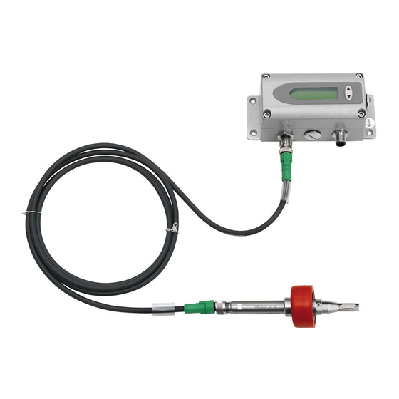
PRODUCT DESCRIPTION The flow meter of the series EE771, based on the measurement principle of thermal mass flow, is suited for the measurement of flow of air and gases in pipelines. Measurement of for instance the consumption of com- pressed air, nitrogen, helium, argon, CO or other non-corrosive and non-flammable gases. -
Page 7: Installation
INSTALLATION 3.1. Mounting dimensions 3.1.1. Model Compact (EE771-A and EE771-B) (4.53) Measurement ball valve Only at DN15: Reduction 3/4“-1/2“ cable gland M16x1.5 Measurment ball valve Thread DN15 1/2" 100±8 (3.94±0.32) (3.62) DN20 or NPT 3/4” (2.83) (3.62) DN25 or NPT 1” (3.27) (4.88) DN32... -
Page 8: Determining Installation Site
3.2. Determining installation site • The installation site should be easy accessible and free of vibrations and shocks • Observe at least 120 mm (5 inch) clearance above the housing with the signal conditioning, in order to be able to remove the sensing probe if necessary. •... -
Page 9: Installation Position
3.3. Installation position Make sure that the arrow on the tip of the sensing probe is pointing in the direction of the flow. Model Vertical Mounting Compact Remote Horizontal Mounting, sensor upwards Horizontal Mounting, sensor downwards Horizontal Mounting, sensor across ++ ... -
Page 10: Required Length Of Straight Pipe
3.4. Required length of straight pipe The flow meter should be installed as far as possible from disturbances of the flow. The causes for disturbance of the flow are for instance, reducers, elbows, T-pieces, valves, gate valves, etc. The specified measurement accuracy can be achieved only when the following straight inlet and outlet pipe lengths are installed: •... -
Page 11: Assembly Of The Measurement Ball Valve
3.5. Assembly of the measurement ball valve • All connections to be made with appropriated sealing material on the threads. • The sealing material should not change the area of the inner cross section of the pipe. It must be warranted that the connections after installation are free of leaks. -
Page 12: Installation Of The Flow Meter Sensing Probe
3.6. Installation of the flow meter sensing probe 3.6.1. Flow direction The flow direction is indicated with an arrow on the tip of the probe. Due to the alignment pin is the installation of the sensing probe in the measurment ball valve only possible in the direction of the flow. After a removal, the sensing probe will be re-installed in the measurement section in exactly the same position as done at the factory. -
Page 13: Electrical Connections
ELECTRICAL CONNECTIONS Before electrical connections are made turn off the power supply first. If not observed the electronics can be damaged as a result. Only a qualified electrotechnical engineer may install the device. • Unscrew the four screws and remove the cover of the housing. •... -
Page 14: Bus Output (Optional)
4.2. Bus Output (optional) 4.2.1. M-Bus (Meter-Bus) The M-Bus (Meter Bus) is a field bus for recording consumption data. Transmission is carried out serially on a reverse polarity protected two-wire line. The flow meter as M-Bus slave requires a separate supply voltage. No specific topology (line or star) is prescribed for the cabling. -
Page 15: Modbus Rtu
Secondary addressing In addition to primary addressing, the EE77x transmitter provides the option of secondary addressing. The fields of identification number, manufacturer, version and medium are used together as the secondary address. The exact sequence of the secondary addressing is described in detail in the M-Bus Standard: http:// www.m-bus.com/files/MBDOC48.PDF. -
Page 16: Control Components
CONTROL COMPONENTS 5.1. Jumper J1 and J2 If the signal output is altered from relay to analogue output or vice versa, Jumper Output 1 has to be relocated. If the analogue output is altered from a current to a voltage output or vice versa, Jumper Out-1 has to be relocated. -
Page 17: Indication Of The Analogue And Pulse Output
Depending on the configuration of the outputs either the measured values, the status of the relay or the consumption is indicated. measurand measuring value unit Maximal : 1.3 m : 323.8 m T : 27.97 °C Measurand SI Unit US Unit Standardized Flow SFPM Temperature... -
Page 18: Reset Of The Consumption Counter Or The Min / Max Value
After that the several different measurement values can be indicated using the UP or DOWN keys. Keep the DOWN or UP key pressed for > 3 sec to exit the MIN / MAX mode. Maximal : 323.8 m 5.3.4. Reset of the consumption counter or the MIN / MAX value Keep both the UP and DOWN key pressed for >... -
Page 19: Maintenance
MAINTENANCE Regular cleaning of the sensor is necessary is used in applications with wet or filthy gases. Cleaning of the sensor is necessary prior to calibration or evaluation. 7.1. Removal of the sensing probe of the flow meter • Shut off the measurement valve with shut-off function (see page 11). -
Page 20: Order Code Miscellaneous
Order Example Order Example EE771-R-AL1N025KC12 EE771-R-CL1N025K Model: Compact ri-le Model: remote probe Working range: Working range: Measuring pipe - diameter: DN25 Measuring pipe - diameter: DN25 Mounting: Measurment ball valve Mounting: Measurement ball valve Plug: 1 plug for power supply and outputs 8.2. -
Page 21: Factory Setting Of Outputs
General Supply voltage 18 - 30 V AC/DC Current consumption max. 200 mA (with display) Temperature range ambient temperature: -20...60 °C (-4...140 °F) medium temperature: -20...80 °C (-4...176 °F) storage temperature: -20...60 °C (-4...140 °F) Nominal pressure up to 16 bar (232 psi) Humidity no condensation... -
Page 22: General
CONFIGURATION SOFTWARE LIMITED LIABILITY E+E Elektronik shall not be held liable for any damages or consequential damages (for example, but not restricted to, loss of earnings, interruption of business, loss of information and data or any other financial losses) resulting from the installation, use or impossibility of use of an E+E Elektronik software product and any associated support services or non-performance of support services. -
Page 23: Installation
Installation In order to set up a smooth installation of the configuration software of the EE771, admin authorization for the personal computer is required. • During installation of the software the EE771 should NOT be connected with the USB cable to the computer. -
Page 24: User Interface
Select the COM-port number as shown in the device manager. These settings are done only once and at the first start of the configuration software. The settings are stored for future use. User Interface Basic information: After retrieving the data from the transmitter, the basic information of the device is shown here. Status message: Here are the messages shown about the status and other information. -
Page 25: Menu Toolbar
Menu toolbar 4.1. File Delete status message deletes the status messages. Exit closes the configuration software. 4.2. Transmitter Read reads the actual configuration of the transmitter. Send uploads the ‘new’ configuration to the transmitter. The following settings are uploaded to the transmitter •... -
Page 26: Output Mode - Analogue
NOTE: The setting “Units” on the tabs for Output 1 and Output 2 are in sync with each other. If the units are changed on one of the output tabs, automatically the units on the other output tab are changed accordingly. 5.1.4. -
Page 27: Output Mode - Pulse
Window The relay is activated as long as the measuring value is between the values of set point 1 and set point 2. The hysteresis of each set point is fixed at 0.2% of the meas- uring range. set point 1 set point 2 e.g.: set point 1 = 100 Nm /h;... -
Page 28: Display
5.3. Display If an optional display is installed, at the tab Display the following items can be entered: Drop-down input field “Display-Mode” • Single spaced • Double spaced (default) Checkbox “Backlight” • Checked = ON • Unchecked = OFF input field “Description (free text), a user specific name (max. -
Page 29: 2-Point Adjustment
upper adjustment point at 80% of measuring range lower adjustment point at 20% of measuring range lower adjustment point automatically at 0% of m.r. upper adjustment point automatically at 100% of m.r. characteristic line before adjustment characteristic line before adjustment 100% 100% characteristic line after adjustment... -
Page 30: Reset To Factory Settings
5.4.3. Reset to factory settings Customer-adjustment can be reset to the factory settings by checking the appropriate checkbox and subse- quently clicking the “reset” button. 5.5. Measuring values overview The tab measuring values provides an overview of the retrieved actual measurement values of the flow meter (transmitter). -
Page 31: Changing The Standard Conditions
5.6.2. Changing the standard conditions The flow meter is factory-set to standard conditions conforming to DIN 1343. Factory setting: P = 1013.25 mbar, t = 0°C (273.15 K) The corrected volume flow measured value is calculated in line with the standard conditions set. 5.6.3. - Page 32 HEAD OFFICE: E+E ELEKTRONIK Ges.m.b.H. Langwiesen 7 A-4209 Engerwitzdorf Austria Tel: +43 7235 605 0 Fax: +43 7235 605 8 info@epluse.com www.epluse.com SALES OFFICES: E+E CHINA / BEIJING Tel: +86 10 84992361 info@epluse.cn www.epluse.cn E+E CHINA / SHANGHAI Tel: +86 21 61176129 info@epluse.cn...
Need help?
Do you have a question about the EE771 Series and is the answer not in the manual?
Questions and answers