Table of Contents
Advertisement
Quick Links
Advertisement
Table of Contents

Subscribe to Our Youtube Channel
Related Manuals for E+E Elektronik EE360


Summary of Contents for E+E Elektronik EE360
- Page 1 User Manual EE360 Moisture in Oil Sensor...
-
Page 2: Table Of Contents
User Manual EE360 Content General Information ............................3 Explanation of Warning Notices and Symbols .................... 3 Safety Instructions ............................. 4 1.2.1. General Safety Instructions ..........................4 1.2.2. Intended Use ..............................4 1.2.3. Alarm Module with Voltages >50 V (Option AM2) ....................5 1.2.4. -
Page 3: General Information
The user manual may not be used for the purposes of competition without the written consent of E+E Elektronik Ges.m.b.H. and may not be forwarded to third parties. Copies may be made for internal purposes. All information, technical data and diagrams included in these instructions are based on the information available at the time of writing. -
Page 4: Safety Instructions
An existing Ethernet connection must be disconnected before opening the housing. 1.2.2. Intended Use EE360 is optimized for reliable measurement in lubrication, hydraulic and insulation oils as well as diesel fuel. In addition to highly accurate measurement of water activity (a ) and temperature (T), EE360 calculates the absolute water content (x) in ppm. -
Page 5: Alarm Module With Voltages >50 V (Option Am2)
1.2.3. Alarm Module with Voltages >50 V (Option AM2) The optional alarm module is isolated from the low-voltage side of EE360 by a special partition; this must remain fitted at all times in the back section of the enclosure. WARNING An open enclosure corresponds to IP00 and exposes components carrying dangerous voltage. -
Page 6: Environmental Aspects
Environmental Aspects PLEASE NOTE Products from E+E Elektronik Ges.m.b.H. are developed and manufactured in compliance with all relevant environmental protection requirements. Please observe local regulations for the disposal of the device. For disposal, the individual components of the device must be separated according to local recycling regulations. -
Page 7: Product Description
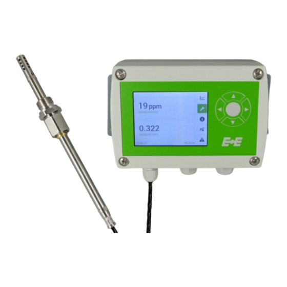
3.5" TFT colour display 5 push-buttons for configuration menu Back section with electrical connection, alarm + supply module and mounting holes Micro USB service interface Standard cable glands / connectors Additional cable gland / connector *) Optional Tab. 2 Parts of the EE360 Moisture in Oil Sensor | 7... -
Page 8: Dimensions
User Manual EE360 Connection terminal block RS485 add-on chip Back section Space for optional modules Front section Mounting plate Fig. 2 Modular enclosure Dimensions Values in mm (inch) Enclosure Polycarbonate 180 (7.09) 166 (6.54) 71 (2.80) 153 (6.02) 5.1 (0.20) - Page 9 User Manual EE360 Probe code “probe cable length” code “probe length” 15 (0.59) (1.3) 1) Refer to ordering guide Probe Minimum insertion depth 23 (1) Probe Maximum insertion depth Max. depth acc. table below Ball valve set G 1/2" ISO or NPT 155 (6.1)
-
Page 10: Mounting And Installation
User Manual EE360 4 Mounting and Installation Mechanical Installation 4.1.1. Mounting of the Enclosure ▪ Drill the mounting holes according to the corresponding mounting pattern below. ▪ Mount the back section of the enclosure with 4 screws (screw diameter <4.2 mm (0.2"), not included in the scope of supply). -
Page 11: Electrical Connection
Electrical Connection NOTICE The electrical installation of the EE360 shall be performed by qualified personnel only. Observe all applicable national and international requirements for the installation of electrical devices as well as for power supply according to EN 61140, class III (EU) and class 2 supply (North America). -
Page 12: Electrical Connection And Wiring
RS485 A (=D+) RS485 B (=D-) EE310/EE360 - Electrical connection for stainless steel housing Ethernet Ethernet Modbus TCP M16x1.5 Ethernet EE310/EE360 - Electrical connection for stainless steel housing (HS2) Ethernet Modbus TCP Power supply + Modbus TCP Modbus TCP Standard Option E4... - Page 13 Power supply + analogue output Modbus RTU n.c. RS485 B n.c. Modbus RTU Power s RS485 B Modbus RTU 1 x M16x1.5 mounted User Manual EE360 M16x1.5 (only with (=D-) Power supply + M16x1.5 1 x M16x1.5 enclosed (=D-) order code J3) analogue output...
- Page 14 Power supply + Modbus RTU analogue output User Manual EE360 rical connection for stainless steel housing (HS2) GND RS485 (shielded) Option Polycarbonate Enclosure Stainless Steel Enclosure Pin Assignment Option AM3 n.c. n.c. RS485 A neutral wire Option E4 Option AM3...
-
Page 15: Probe Mounting
For direct probe installation shut-off valves shall be placed on both sides of the probe insert (see Fig. 7 Installation of the EE360 probe directly into the process). This allows the sensor probe to be easily removed for maintenance and calibration. -
Page 16: Installation Of The Probe With Ball Valve Set
≥13.1 mm (0.55") Stop valve Fig. 7 Installation of the EE360 probe directly into the process 4.4.2. Installation of the Probe with Ball Valve Set The ball valve set allows for installation and removal of the probe without process interruption. - Page 17 User Manual EE360 Metal sealing ring (as a standard contained with the ball valve set) Metal sealing ring (as a standard contained with the probe) 1/2" ball valve Extension Clamping sleeve (is not available for an NPT thread) Lock nut...
-
Page 18: Optional Modules
User Manual EE360 5 Optional Modules Alarm Module (Option AM2) The module offers two freely configurable relay outputs for alarm or control purposes. Various operation modes are available including switch hysteresis, switch window and error indication. The error modes can be configured independently from each other. - Page 19 User Manual EE360 Switch Window Mode The switching behavior is determined by entering two switching points and two associated hysteresis values. RH [%] Switching point 2 Hysteresis 2 Switching point 1 Hysteresis 1 open Terminal 1-2 / 4-5 Normal state: Standard...
-
Page 20: Integrated Power Supply 100 - 240 V Ac (Option Am3)
When error indication mode is selected, various errors will trigger the alarm output. An alarm output in this operation mode is used for error indication only. Integrated Power Supply 100 - 240 V AC (Option AM3) This module allows the EE360 to be powered with 100 - 240 V AC (50/60 Hz), 2 VA. Enclosure Polycarbonate Stainless steel Fig. -
Page 21: Rs485 Module - Modbus Rtu (Option J3)
User Manual EE360 RS485 Module - Modbus RTU (Option J3) Instructions for Modbus-Protocol-Setup please see Application Note AN0103 (www.epluse.com/ee360). Up to 32 EE360 sensors with Modbus RTU interface can be connected in a RS485 bus system. Slave n Slave 2 (max. -
Page 22: Available Tcp And Udp Ports
The unit identifier of the MBAP header is not used and can be any value from 0 to 255. HTTP-Webserver (Port 80) For a quick communication check enter the desired IP in a web browser and connect with the EE360 Ethernet Module’s Webserver. -
Page 23: Retrofit With Ethernet Module
Supported Ethernet standard: 802.3i/u/x and af. IPv6 is not supported. 5.4.3. Retrofit with Ethernet Module The EE360 can be retrofitted with an Ethernet Module. Before retrofitting please make sure, that the EE360 firmware is updated to the latest version by using the Product Configuration Software PCS10. ▪... -
Page 24: Modbus Rtu Example
Modbus protocol settings 0x01 1) Register number starts from 1. 2) Protocol address starts from 0. 3) For Modbus protocol settings see Application Note Modbus AN0103 (available at www.epluse.com/ee360). Tab. 9 EE360 registers for device setup Modbus RTU Example The EE360’s Modbus address is 231 [E7 in HEX]. -
Page 25: Pluggable Probe (Option Pc4)
6 Setup and Configuration The EE360 is ready to use and does not require any configuration by the user. The factory setup of EE360 corresponds to the type number ordered. For ordering guide please see datasheet at www.epluse.com/ee360. -
Page 26: Configuration Interface
Factory setup can be changed by using a USB configuration cable (USB-C to USB-A, accessory order code HA010327) and the PCS10 Product Configuration Software. The EE360 is powered by the PC via the USB interface, no additional power supply shall be applied. -
Page 27: Tft Colour Display (Optional)
3.5" TFT Colour Display (optional) The EE360 display includes a data logger and push buttons for full configuration of the device. Upon start-up of an EE360 with display, the data logger and the configuration menu will be initialized during the first 5 seconds. -
Page 28: Configuration Menu
User Manual EE360 One point Fig. 25 Logging graph The data logging continues even when the data memory is full; new data is stored while the oldest data is deleted (first in first out memory). The last 20 000 logged values are available in the internal memory. The logged data can be downloaded with PCS10 Product Configuration Software as .csv file by choosing the measurands and the time period. -
Page 29: Status Information
User Manual EE360 Status Information The status information shows all actual EE360 settings. Fig. 27 Status information Buzzer ON / OFF Icon Function Buzzer ON Buzzer OFF Tab. 11 Explanation of the icons Error Indication When an error occurs, the error indication shows the error code. -
Page 30: Error Messages Via Leds
User Manual EE360 Error Category Description Non-critical error, can be solved by the user. ▪ The display blinks and the buzzer beeps every 10 seconds. ▪ The red status LED lights continuously. Critical error, return the device to E+E for service. -
Page 31: Sensor Replacement
Screw on a new filter cap with upmost care not to touch the sensors. Bend the filter cap’s locking mechanism to the inside. Perform a 2-point humidity adjustment of the EE360 with the PCS10 Product Configuration Software or with the display and push buttons. -
Page 32: Moisture And Temperature Calibration And Adjustment
(comparison with a reference) or adjustment (bringing the device in line with a reference) The EE360 can be calibrated / adjusted with the help of the PCS10. For this purpose, the probe needs to be connected to a PC via a Modbus configuration adapter. - Page 33 User Manual EE360 adjusted measured value current measured value Reference value Fig. 31 Offset adjustment 1/2 OUTPUT SCALE ADJUSTMENT POINT LOW ADJUSTMENT POINT HIGH Adjustment point NEW current measurement upper limit output scale (or last calibration point HIGH) lower limit output scale...
-
Page 34: Spare Parts And Accessories
Ball valve set 1/2" NPT HA050104 Ethernet module for retrofitting polycarbonate enclosure HA010606 for remote probe 1) Only for devices with pluggable probe option PC4. 2) For polycarbonate enclosure only. Two pieces are necessary for each EE360. Moisture in Oil Sensor | 34... -
Page 35: Technical Data
< 500 Ohm = load resistance 0 - 20 mA 3-wire < 500 Ohm Digital Digital interface RS485 (EE360 = 1 unit load) Protocol Option J3 Modbus RTU Factory settings 9 600 Baud, parity even, 1 stop bit, Modbus address 231 Supported Baud rates 300, 600, 1200, 2400, 4800, 9600, 19200, 38400, 57600 and 76800... - Page 36 User Manual EE360 General 8 - 35 V DC 12 - 30 V AC Power supply class III 100 - 240 V AC, 50/60 Hz USA & Canada: Class 2 supply necessary, max. voltage 30 V DC Current consumption, typ.
-
Page 37: Appendix
User Manual EE360 10 Appendix 10.1 Overview Menu Data-logging Configuration of data logger/graph - sampling rate | graphs Display settings Setting of display layout - measurands | brightness | display alarm Analog output Output configuration - mode | measurands | scaling | error indication... -
Page 38: Detailed Information
User Manual EE360 10.2 Detailed Information Menu Data-logging 1 s / 10 s Sampling rate 1 min / 5 min / 15 min / 30 min 1 h / 5 h / 12 h Measurand Water activity [a Axis 1... - Page 39 User Manual EE360 Menu Analog output Output 1 Output number Output 2 Current Mode Voltage Water activity [a Water content [ppm] Measurand Rel. humidity [%] Temperature [°C] Temperature [°F] Analog range Value Temperature [K] Scaling Value Cancel Error indication Fig. 36...
- Page 40 User Manual EE360 Menu Device settings German English Language Chinese (simplified) French Date Date settings dd.mm.yy Date format mm.dd.yy yyyy-mm-dd Time Time settings hh:mm:ss Date and time Time format hh:mm Daylight saving Central europe time UTC date Date settings UTC settings...
-
Page 41: Optional Menu
Hysteresis Switch window Switching point Switching point high Hysteresis Standard Normal state Inverted Standard Error indication Normal state Inverted * Menu only available with connected alarm module during EE360 start-up Fig. 40 Alarm output Moisture in Oil Sensor | 41... - Page 42 Baudrate value None Parity Even Stop bits Value Value Address * Menu only available with connected Modbus RTU module during EE360 start-up. Fig. 41 Modbus settings Menu IP settings Type shows the status of the DHCP setting IP address Value...
-
Page 43: Conformity
User Manual EE360 11 Conformity 11.1 Declarations of Conformity E+E Elektronik Ges.m.b.H. hereby declares that the product complies with the respective regulations listed below: European directives and standards. UK statutory instruments and designated standards. Please refer to the product page at www.epluse.com/ee360... - Page 44 T +39 02 2707 86 36 info.it@epluse.com E+E Elektronik Korea Ltd. T +82 31 732 6050 info.kr@epluse.com E+E Elektronik Corporation T +1 847 490 0520 info.us@epluse.com Version v2.2 | 08-2023 | 194475 © Copyright E+E Elektronik Ges.m.b.H. | Modification rights reserved.
Need help?
Do you have a question about the EE360 and is the answer not in the manual?
Questions and answers