Sign In
Upload
Manuals
Brands
E+E Elektronik Manuals
Measuring Instruments
EE771 Series
User Manuals: E+E Elektronik EE771 Series Flow Meter
Manuals and User Guides for E+E Elektronik EE771 Series Flow Meter. We have
2
E+E Elektronik EE771 Series Flow Meter manuals available for free PDF download: User Manual, Manual
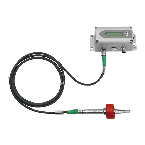
E+E Elektronik EE771 Series User Manual (48 pages)
Flow Sensor for Compressed Air and Gases DN15 (1/2")-DN50 (2")
Brand:
E+E Elektronik
| Category:
Security Sensors
| Size: 8 MB
Table of Contents
Table of Contents
2
General Information
4
Explanation of Warning Notices and Symbols
4
Safety Instructions
5
General Safety Instructions
5
Intended Use
5
Mounting, Start-Up and Operation
5
Environmental Aspects
6
Scope of Supply
6
Product Description
7
General
7
Dimensions
8
Display
9
Mounting and Installation
10
Determining Installation Site
10
Process Pressure
10
Installation Position
11
Required Length of Straight Pipe
12
Assembly of the Measurement Ball Valve
13
Assembly Without Flow Sensor, but with Screw Cap Instead (Blind Cap)
13
Shut off the Measurement Ball Valve
14
Installation of the Flow Sensing Probe
14
Flow Direction
14
Installation of the Sensing Probe
14
Electrical Connection
16
Connection Diagram
16
Relay and Pulse Output, Internal Switching
17
Connection with Optional Plug for Power Supply and Outputs (Order Code E4)
17
Setup and Configuration
18
Jumpers for Output Configuration
18
USB Configuration Interface
18
Display / Indicator with Keypad (Optional)
19
Indication of the Analogue and Pulse Output
19
Indication of the Switch Output
19
Indication Of The Min / Max Values
20
Reset Of The Consumption Meter Or The Min / Max Value
20
Maximum Consumption Meter
20
Bus Output (Optional)
21
M-Bus (Meter-Bus)
21
Modbus RTU Register Map
22
Data Transmission
23
Device Address
24
Maintenance and Service
24
Error Messages
24
Maintenance
24
Cleaning the Sensing Element of the Flow Sensor
25
Repairs
25
Replacement Parts / Accessories
26
Order Code Replacement Sensor
26
Order Code Miscellaneous
27
Technical Data
28
Configuration Software
32
Introduction
32
Installation
32
User Interface
34
Menu Toolbar
35
File
35
Transmitter
35
Extras
35
Input Screen
35
Output 1, Output 2
35
Minimum Flow Shutdown
39
Display
39
Adjustment
39
Measuring Values Overview
41
Setting up Process Parameters
42
External Pressure Sensor for Pressure Compensation
43
Bus Configuration
43
Conformity
44
Declarations of Conformity
44
FCC Part 15 Compliance Statement
44
ICES-003 Compliance Statement
44
Advertisement
E+E Elektronik EE771 Series Manual (32 pages)
FLOW METER for COMPRESSED AIR and GASES
Brand:
E+E Elektronik
| Category:
Measuring Instruments
| Size: 5 MB
Table of Contents
Table of Contents
3
General
4
Safety Instructions
4
Intended Use
4
Installation, Start up and Control
5
Environmental Aspects
5
Product Description
6
Installation
7
Mounting Dimensions
7
Model Compact (EE771-A and EE771-B)
7
Model Remote Sensing Probe (EE771-C)
7
Determining Installation Site
8
Process Pressure
8
Installation Position
9
Required Length of Straight Pipe
10
Assembly of the Measurement Ball Valve
11
Assembly Without Flow Meter, but with Screw Cap Instead (Blind Cap)
11
Shut off the Measurement Ball Valve
11
Installation of the Flow Meter Sensing Probe
12
Flow Direction
12
Installation of the Sensing Probe
12
Electrical Connections
13
Connection Diagram
13
Relay and Pulse Output, Internal Switching
13
Connection with Optional Plug for Power Supply and Outputs (Order Code Q)
13
Bus Output (Optional)
14
M-Bus (Meter-Bus)
14
Modbus RTU
15
Data Transmission
15
Addressing
15
Control Components
16
Jumper J1 and J2
16
Digital Interface USB (for Configuration)
16
Display / Indicator with Keypad (Optional)
16
Indication of the Analogue and Pulse Output
17
Indication of the Switch Output
17
Indication of the MIN / MAX Values
17
Reset of the Consumption Counter or the MIN / MAX Value
18
Maximum Consumption Counter
18
Error Messages
18
Maintenance
19
Removal of the Sensing Probe of the Flow Meter
19
Cleaning of the Sensor of the Flow Meter
19
Replacement Parts / Accessories
19
Order Code Replacement Sensor
19
Order Code Miscellaneous
20
Technical Data
20
Factory Setting of Outputs
21
General
22
Installation
23
Configuration of the USB Interface (Virtualcom)
23
User Interface
24
Menu Toolbar
25
File
25
Transmitter
25
Extras
25
Input Screen
25
Output 1, Output 2
25
Output Mode
25
Measurand
25
Units
25
Output Mode - Analogue
26
Output Mode - Switch (Relay)
26
Output Mode - Pulse
27
Minimum Flow Shutdown
27
Display
28
Adjustment
28
1-Point Adjustment
28
2-Point Adjustment
29
Reset to Factory Settings
30
Measuring Values Overview
30
Reset of the MIN / MAX Values
30
Reset of the Consumption Counter (Totalizer)
30
Setting up Process Parameters
30
Change the Process Gas
30
Changing the Standard Conditions
31
Pressure Compensation
31
External Pressure Transmitter for Pressure Compensation
31
Bus Configuration
31
Advertisement
Related Products
E+E Elektronik EE771-B
E+E Elektronik EE771-A
E+E Elektronik EE771-C
E+E Elektronik EE776 Series
E+E Elektronik EE772
E+E Elektronik EE772-A
E+E Elektronik EE772-B
E+E Elektronik EE772-C
E+E Elektronik EE872 Series
E+E Elektronik EE872-M15
E+E Elektronik Categories
Transmitter
Accessories
Measuring Instruments
Security Sensors
Temperature Controller
More E+E Elektronik Manuals
Login
Sign In
OR
Sign in with Facebook
Sign in with Google
Upload manual
Upload from disk
Upload from URL