
Related Manuals for E+E Elektronik EE212


Summary of Contents for E+E Elektronik EE212
- Page 1 User Manual EE212 Modular Humidity / Temperature Sensor BA_EE212 // v1.0 // Modification rights reserved...
- Page 2 E+E Elektronik Ges.m.b.H. does not accept warranty and liability claims neither upon this publication nor in case of improper treatment of the described products. The document may contain technical inaccuracies and typographical errors. The content will be revised on a regular basis.
-
Page 3: Table Of Contents
CONTENT General ..............................4 Explanation of Symbols ..........................4 Safety Instructions ............................4 1.2.1 General Safety Instructions ..........................4 1.2.2 Intended Use ................................4 1.2.3 Mounting, Start-up and Operation ........................5 Environmental Aspects ..........................5 ESD Protection .............................5 Scope of Supply ..........................5 Product Description ..........................5 General ................................5 Dimensions ..............................6 Electrical Connection .............................6 Display ................................8... -
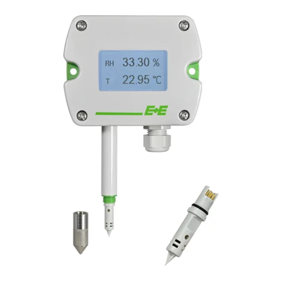
Page 4: General
It is available for wall or duct mounting. The use of the EE212 in any other way than described in this manual bears a safety risk for people and the entire measurement installation and is therefore not allowed. -
Page 5: Mounting, Start-Up And Operation
1.2.3 Mounting, Start-up and Operation The EE212 has been produced under state of the art manufacturing conditions, has been thoroughly tested and has left the factory after fulfilling all safety criteria. The manufacturer has taken all precautions to ensure safe operation of the device. The user must ensure that the device is set up and installed in a manner that does not have a negative effect on its safe use. -
Page 6: Dimensions
The pluggable sensing module can easily be exchanged on-site with only short downtime. Refer to chapter 6.1 for details on sensing module exchange. For a setup deviating from default, the EE212 can be configured manually by means of the free EE- PCS Product Configuration Software. Refer to chapter 5 Setup and Configuration for details. - Page 7 Off .... no USB connection to PC Configuration connector (USB configuration adapter) FFC cable socket for the display Screw terminals for power supply and analogue outputs Screw terminals, do not connect Output signal (I / U) selection Tab. 1 EE212 electronics board components Modular Humidity / Temperature Sensor...
-
Page 8: Display
ƒ Setup and Configuration The EE212 is ready to use and does not require any configuration by the user. The factory setup of EE212 corresponds to the type number ordered. Please refer to the data sheet at www.epluse.com/ EE212. If needed, the user can change the factory setup with the help of the free EE-PCS Product Configuration Software and the USB configuration adapter (HA011066). - Page 9 Analogue output configuration options: Measurand assignment ƒ Current and/or voltage scaling ƒ Unit selection ƒ Output value fixing (measured value or current/voltage value) ƒ Fig. 4 EE212 with current or voltage output (selectable) Fig. 5 EE212 with current output Modular Humidity / Temperature Sensor...
- Page 10 Display configuration options: Display layout ƒ Measurand selection ƒ Display appearance (backlight, brightness, contrast) ƒ Fig. 6 EE212 display configuration Modular Humidity / Temperature Sensor...
-
Page 11: Maintenance And Service
Location of EE212M serial number 2D bar code Fig. 8 EE212 modular construction Power off EE212 before connecting or disconnecting the sensing module. Failing to do so may cause damages to EE212 and to the module. Procedure: Power off the EE212. -
Page 12: Filter Cap Exchange
When connecting the display’s FFC cable to the EE212 electronics board, please observe the correct orientation. The blue cable stiffener needs to be on the left side as shown in Fig. 9. Power off EE212 before connecting or disconnecting the display. Failing to do so may cause damages to EE212 and to the display. -
Page 13: Technical Data
Technical Data Measurands Relative Humidity Working range 0...100 %RH Accuracy (incl. hysteresis, non-linearity and repeatability) @ 23 °C ±(1.5 + 0.005*mv) %RH (73 °F) mv = measured value -15...60 °C ±(1.8 + 0.007*mv) %RH (5...140 °F) -40...-15 °C Additional uncertainty ±0.125 %RH/°C (-40...5 °F) Temperature ±... - Page 14 HEADQUARTERS SUBSIDIARIES E+E Elektronik Ges.m.b.H. E+E Elektronik China E+E Elektronik Germany E+E Elektronik Korea Langwiesen 7 18F, Kaidi Financial Building, Schöne Aussicht 8 C Suite 2001, Heungdeok IT 4209 Engerwitzdorf No.1088 XiangYin Road 61348 Bad Homburg Valley Towerdong, 13, Austria 200433 Shanghai Tel.:...
Need help?
Do you have a question about the EE212 and is the answer not in the manual?
Questions and answers