Subscribe to Our Youtube Channel
Summary of Contents for E+E Elektronik EE872 Series
- Page 1 User Manual EE872 Modular Probe for CO , RH, T and p BA_EE872_e // V1.2 // technical data are subject to change...
- Page 2 E+E Elektronik Ges.m.b.H. doesn‘t accept warranty and liability claims neither upon this publication nor in case of improper treatment of the described products. The document may contain technical inaccuracies and typographical errors. The content will be revised on a regular basis. These changes will be implemented in later versions. The described products can be improved and changed at any time without prior notice.
-
Page 3: Table Of Contents
CONTENTS General ..............................4 Explanation of Symbols ..........................4 1.1.1 General Safety Instructions ..........................4 Environmental Aspects ..........................4 1.2.1 Mounting and Start-up ............................5 Scope of Supply ..........................5 Accessories ..............................5 Spare Parts ..............................5 Product Description ..........................6 Operation Principle ............................6 Dimensions in mm (inch) ..........................6 Connectivity ..............................7 Selection between Analogue Output and RS485 Interface ................7 Installation ............................8... -
Page 4: General
This symbol indicates safety information. It is essential that all safety information is strictly observed. Failure to comply with this information can lead to personal injuries or damage to property. E+E Elektronik® assumes no liability if this happens. This symbol indicates instructions. -
Page 5: Mounting And Start-Up
1.2.1 Mounting and Start-up The device has been produced under state of the art manufacturing conditions, has been thoroughly tested and has left the factory fulfilling all safety criteria. The manufacturer has taken all precautions to ensure safe operation of the device. The user must ensure that the device is set up and installed in a manner that does not have a negative effect on its safe use. -
Page 6: Product Description
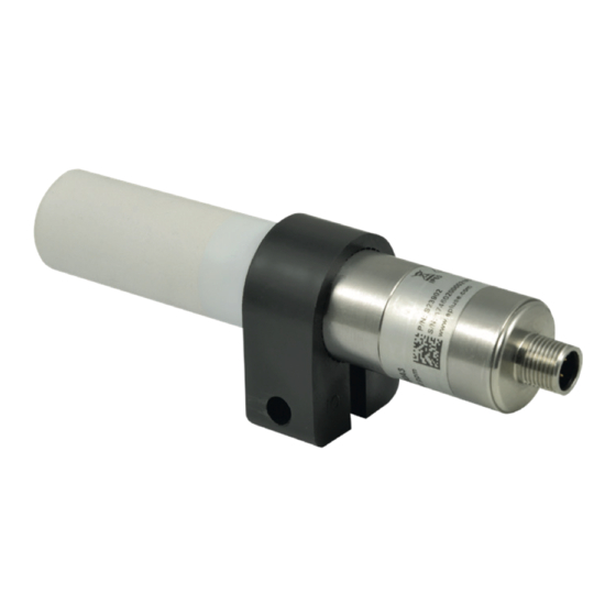
Product Description Operation Principle The EE872 is available in three versions (see also Fig. 5) EE872-M10...: The probe measures the CO concentration. The sensing module is heated by factory default setting to prevent condensation. The CO measurement value is available on the analogue output or on the digital interface. -
Page 7: Connectivity
Fig. 2 Dimensions of optional radiation shield (accessory HA010510) Connectivity Pin number Function Wire colors for accessories: - Couplig flange HA010705 Voltage output - Connection cable HA010819/820/821 Current output Supply voltage brown B RS485 (D-) or voltage output white front view front view blue GND analogue output... -
Page 8: Installation
Installation Best measurement performance is achieved when the entire probe is located inside the environment to be monitored. This is the case, for example, when the EE872 is fixed onto a wall with the mounting clip HA010227 (not included in the scope of supply, see data sheet “Accessories”), or freely hangs from the ceiling on the connection cable. -
Page 9: Ee-Pcs Product Configuration Software
EE-PCS Product Configuration Software 1. Download the EE-PCS Product Configuration Software from www.epluse.com/configurator install it on the PC. 2. Connect the E+E device to the PC using the Modbus configuration cable. 3. Start the EE-PCS software. 4. Follow the instructions on the EE-PCS opening page for scanning the ports and identifying the connected device. -
Page 10: Modbus Register Map
5.2.2 Modbus Register Map The measured data is saved as 32 bit floating point values (data type FLOAT) and as 16 bit signed integer values (data type INTEGER): FLOAT 32 bit Parameter Unit Register number [DEC] Protocol address [HEX] Read register: function code 0x03 / 0x04 CO2 (average) 1061 0x424... -
Page 11: Error Indication On The Analogue Output (Namur)
Decoding of float values: Float values are stored according IEEE754 standard. The byte pairs 1, 2 and 3, 4 are inverted as fol- lows: MMMMMMMM MMMMMMMM SEEEEEEE EMMMMMMM Byte 3 Byte 4 Byte 1 Byte 2 Example: Response [Hex] Value in decimal Byte 1 (Register 2 - Hi) Byte 2 (Register 2 –... -
Page 12: Changing The Filter Cap
Changing the Filter Cap In a dusty, polluted environment it might be necessary to replace the filter cap once in a while. In most of the cases, a clogged filter shows visible contamination or dirt. Longer response time of the CO measurement also indicates a clogged filter cap. -
Page 13: Technical Data
Technical Data Measurands Measurement principle Dual wavelength non dispersive infrared (NDIR) Measurement range 0...2 000 ppm: < ± (50 ppm + 2 % mv) mv = CO measured value Accuracy at 25 °C 0...5 000 ppm: < ± (50 ppm + 3 % mv) (77 °F) 1013 mbar 0...10 000 ppm: <... - Page 14 HEADQUARTERS SUBSIDIARIES E+E Elektronik Ges.m.b.H. E+E Elektronik Germany E+E Elektronik France E+E Elektronik Korea Langwiesen 7 info@epluse.de info@epluse.fr Tel: +82 31 732 6050 A-4209 Engerwitzdorf Tel: +33 4 74 72 35 82 info@epluse.co.kr Office Bad Homburg Austria Tel: +49 6172 13881-0...


Need help?
Do you have a question about the EE872 Series and is the answer not in the manual?
Questions and answers