Table of Contents
Advertisement
Quick Links
USER MANUAL
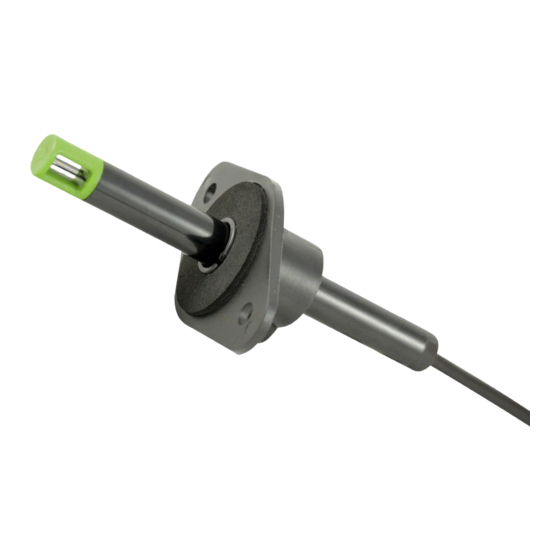
EE671 - Miniature Air Flow Probe
GENERAL
The EE671 air velocity sensor operates on the hot-film anemometer principle and features an innovative, very robust E+E
sensing element manufactured in thin-film technology combined with innovative transfer-molding.
The mounting flange allows for correct positioning and easy adjustment of the immersion depth.
EE671 is dedicated for accurate and reliable measurement in building automation and ventilation applications. For special
applications do not hesitate to contact the manufacturer or their local distributor.
CAUTION
•
Accurate measurement results are conditioned by the correct positioning of the probe in the air stream. Best accuracy is
achieved in laminar flow.
•
Observe the minimum inlet and outlet path length, see page 4.
•
Avoid mechanical stress on the probe and especially onto the sensing head.
•
Observe the humidity working range 5...95 % RH, non-condensing.
•
Avoid installation in corrosive environment, as this may lead to sensor destruction.
ELECTRICAL CONNECTION
Important note:
The manufacturer cannot be held responsible for personal injuries or damage to property as a result of incorrect handling,
installation, wiring, power supply and maintenance of the device.
Please note:
The device may only be powered with a power supply class III
ƒ
EE671 is an ESD-sensitive device. It is neither short-circuit-proof, nor surge-proof. The digital communication lines
ƒ
may not be connected to the supply lines.
Pin number
4
3
5
1
2
front view on
M12 sensor plug
Accessory HA0108xx - connecting cable
DIMENSIONS mm (inch)
Cable version:
15 (0.6")
Plug version:
15 (0.6")
Flange:
Wire colour
1
grey
2
brown
3
green
4
yellow
5
white
130 (5.12")
115 (4.53")
Führungssteg / alignment strip
121 (4.76")
106 (4.17")
Führungssteg / alignment strip
80 (3.14")
60 (2.4")
Detail A
(Europe) or with a class 2 supply (North America).
Analogue
output
SDA (digital setup interface E2)
GND
AV = Analogue output
SCL (digital setup interface E2)
V+ = Supply voltage
Analogue
1
brown
SDA (digital setup interface E2)
2
white
GND
3
blue
AV = Analogue output
4
black
SCL (digital setup interface E2)
5
grey
V+ = Supply voltage
10 (0.4")
15.8 (0.62")
Digital
interface
V+ = Supply voltage
RS485 B (D-)
GND
RS485 A (D+)
n.c.
output
Digital
V+ = Supply voltage
RS485 B (D-)
GND
RS485 A (D+)
n.c.
Front view sensor head:
13.4 (0.53")
Führungssteg /
alignment strip
Recess for alignment strip
Detail A:
interface
1
Advertisement
Table of Contents

Related Manuals for E+E Elektronik EE671


Summary of Contents for E+E Elektronik EE671
- Page 1 EE671 - Miniature Air Flow Probe GENERAL The EE671 air velocity sensor operates on the hot-film anemometer principle and features an innovative, very robust E+E sensing element manufactured in thin-film technology combined with innovative transfer-molding. The mounting flange allows for correct positioning and easy adjustment of the immersion depth.
- Page 2 Quick guide MODBUS RTU The EE671 air flow probe represents 1 unit load in a Modbus RTU network. For Modbus protocol settings see Modbus Application Note AN0103 (www.epluse.com/ee671). Factory settings: Modbus address 238, Baud rate 9 600, even parity, 1 stop bit. The Modbus address can be customised in the register 0x00 (value margin 1 - 247 permitted).
- Page 3 (2.4") (2.4") The mounting flange allows also for precise setting of the EE671 immersion depth. The entire sensing head must be in the air flow to be measured. CORRECT INCORRECT...
- Page 4 MOUNTING GUIDELINES FOR AIR VELOCITY MEASURING DEVICES For accurate measurement results it is of paramount importance to place the sensing probe at a location with low turbulence, such as after filters, rectifiers, heaters or coolers. Turbulence appears after obstructions like fans, bends, junctions or section changes in the duct (diffusers / confusers), so the probe shall be placed far enough from these.
- Page 5 ICES-003 Issue 5: CAN ICES-3 B / NMB-3 B INFORMATION +43 7235 605 0 / info@epluse.com E+E Elektronik Ges.m.b.H. Langwiesen 7 • 4209 Engerwitzdorf • Austria Tel: +43 7235 605-0 • Fax: +43 7235 605-8 info@epluse.com • www.epluse.com LG Linz Fn 165761 t • UID-Nr. ATU44043101 Place of Jurisdiction: A-4020 Linz •...
Need help?
Do you have a question about the EE671 and is the answer not in the manual?
Questions and answers