Table of Contents
Advertisement
Quick Links
Advertisement
Table of Contents

Subscribe to Our Youtube Channel
Related Manuals for E+E Elektronik EE660


Summary of Contents for E+E Elektronik EE660
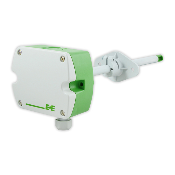
- Page 1 User Manual EE660 Low Air Velocity Sensor...
-
Page 2: Table Of Contents
User Manual EE660 Content General Information ............................3 Explanation of Warning Notices and Symbols .................... 3 Safety Instructions ............................. 4 1.2.1. General Safety Instructions ..........................4 1.2.2. Intended Use ..............................4 1.2.3. Mounting, Start-up and Operation ........................4 Environmental Aspects..........................5 Scope of Supply .............................. -
Page 3: General Information
All rights reserved by E+E Elektronik Ges.m.b.H. No part of this document may be reproduced, published or publicly displayed in any form or by any means, nor may its contents be modified, translated, adapted, sold or disclosed to a third party without prior written permission of E+E Elektronik Ges.m.b.H. -
Page 4: Safety Instructions
Use the EE660 only as intended and observe all technical specifications. 1.2.2. Intended Use The EE660 low air velocity sensor is dedicated for accurate and reliable measurement in laminar flow control and special ventilation applications, for instance in clean rooms. WARNING Non-compliance with the product documentation may cause safety risks for people and the entire measurement installation. -
Page 5: Environmental Aspects
Environmental Aspects PLEASE NOTE Products from E+E Elektronik Ges.m.b.H. are developed and manufactured in compliance with all relevant environmental protection requirements. Please observe local regulations for the disposal of the device. For disposal, the individual components of the device must be separated according to local recycling regulations. -
Page 6: Product Description
Modbus RTU or BACnet MS/TP protocol. The air velocity can also be read on the optional display. The measuring range and the response time of the EE660 can be configured via jumpers on the electronics board (refer to chapter 6.1 Analogue Settings) or with the software. -
Page 7: Mounting And Installation
>16 (0.63) Air flow 60 (2.4) The arrow engraved on the sensing head of EE660 indicates the direction of the air stream during factory adjustment. When installing the EE660 probe, make sure that the arrow matches exactly the flow direction. -
Page 8: Positioning Of Air Velocity Sensor In A Ventilation Duct
Correct Incorrect Air flow Air flow The mounting flange allows for precise setting of the EE660 immersion depth in a duct. The entire sensing head must be in the air flow to be measured. Correct Incorrect Immersion depth = 30...50 %... - Page 9 User Manual EE660 Incorrect positioning Correct positioning Description Mounting the sensing probe in the centre of the duct. The optimal position is after the filter. Please ensusre sufficient distance. <6D >6D <6D >6D <6D >6D <6D >6D <6D <6D >6D >6D...
-
Page 10: Electrical Connection
The manufacturer cannot be held responsible for personal injuries or damage to property as a result of incorrect handling, installation, wiring, power supply and maintenance of the device. The EE660 features screw terminals for connecting the power supply and the outputs. The cables are fed into the enclosure through the M16 cable gland. -
Page 11: Rs485 Interface
Connection diagram for RS485 interface 6 Setup and Configuration Analogue Settings For performing the EE660 settings via the PCS10 Product Configuration Software (free download from www.epluse.com/pcs10) the jumper for the measuring range must be set to HI. Selection of response the time t Selection of measuring range 6.1.1. -
Page 12: Selection Of Measuring Range
(factory setting) RS485 Digital Interface The EE660 is ready to use and does not require any configuration by the user. The factory setup of the EE660 corresponds to the type number ordered. Please refer to the datasheet at www.epluse.com/ee660. If needed, the user can change the factory setup with the help of the free PCS10 Product Configuration Software and the Modbus configuration adapter (HA011066). -
Page 13: Device Address
Tab. 2 BACnet protocol settings PLEASE NOTE The recommended settings for multiple devices in a BACnet MS/TP network are 38 400, 8, none, 1. The EE660 PICS (Product Implementation Conformance Statement) is available on the E+E website at www.epluse.com/ee660. BACnet address and baud rate can be set via: ▪ PCS10 Product Configuration Software and the USB configuration adapter HA011066. -
Page 14: Modbus Rtu Protocol Settings
The recommended settings for multiple devices in a Modbus RTU network are 9600, 8, even, 1. ▪ The EE660 represents 1 unit load on an RS485 network. Device address, baud rate, parity and stop bits can be set via: ▪... -
Page 15: Modbus Register Map
4022 1) The choice of measurement units (metric or non-metric) must be done according to the ordering guide, refer to EE660 datasheet. Switching from metric to non-metric or vice versa by using the PCS10 is not possible. 2) Register number (decimal) starts from 1 3) Register address (hexadecimal) starts from 0 4) Examples: For scale 100, the reading of 2550 means a value of 25.5. -
Page 16: Modbus Rtu Example
Please refer to ▪ MODBUS APPLICATION PROTOCOL SPECIFICATION V1.1b3, chapter 6: www.modbus.org/docs/Modbus_Application_Protocol_V1_1b3.pdf ▪ E+E Application Note Modbus AN0103 (available at www.epluse.com/ee660) Read the temperature (FLOAT32) T = 26.652524 °C from the register 0x03EA: Master (e.g. PLC) EE660 Request [Hex]: Modbus... -
Page 17: Repairs
< 450 Ω = load resistance Scaling area 0...1 m/s / 0...1.5 m/s / 0...2 m/s (selectable by jumper, only for analogue output) Digital Digital interface RS485 (EE660 = 1 unit load) Protocol Modbus RTU Factory settings 9 600 Baud, parity even, 1 stop bit, Modbus address 65 Supported Baud rates 9 600, 19 200 and 38 400... - Page 18 User Manual EE660 General 24 V AC / DC ±20 % Power supply class III USA & Canada: Class 2 supply necessary Current consumption, max. AC supply - DC supply - AC supply - DC supply - no display no display with display with display Analogue output...
-
Page 19: Conformity
User Manual EE660 10 Conformity 10.1 Declarations of Conformity E+E Elektronik Ges.m.b.H. hereby declares that the product complies with the respective regulations listed below: European directives and standards. UK statutory instruments and designated standards. Please refer to the product page at www.epluse.com/ee660... - Page 20 T +39 02 2707 86 36 info.it@epluse.com E+E Elektronik Korea Ltd. T +82 31 732 6050 info.kr@epluse.com E+E Elektronik Corporation T +1 847 490 0520 info.us@epluse.com BA_EE660 | Version v1.3 | 06-2024 © Copyright E+E Elektronik Ges.m.b.H. | All rights reserved.
Need help?
Do you have a question about the EE660 and is the answer not in the manual?
Questions and answers