E+E Elektronik EE600 Quick Manual
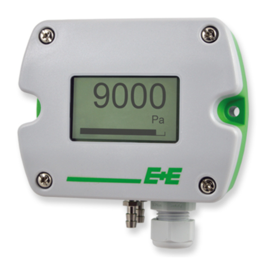
Differential pressure sensor
Hide thumbs
Also See for EE600:
- User manual (30 pages) ,
- Operation manual (16 pages) ,
- Quick manual (2 pages)
Table of Contents
Advertisement
Quick Links
QUICK GUIDE
EE600 - Differential Pressure Sensor
Find this document and further product information on our website at www.epluse.com/ee600.
Installation
Pressure Connection
Use a Ø7.5 mm drill for installing the pressure connection nipples into the duct.
User Interface - LED Indication
Green LED
Flashing (1s interval)
One flash (2s)
Off
Fast flashing
(0.2 s interval)
Connection Diagram
Important note:
The manufacturer cannot be held responsible for personal injuries or damage to property as a result of incorrect handling,
installation, wiring, power supply and maintenance of the device.
Analogue Output
Power supply
15 - 35 V DC
24 V AC ±20 %
EE600 with Analogue Output
1)
S1
S2
MR
0
0
100 %
1
0
75 %
0
1
50 %
1
1
25 %
1) Measuring range
2) Display backlight
switch S9 = 1. Only available with version with 10 DIP switches.
INFORMATION
E+E Elektronik Ges.m.b.H.
Langwiesen 7 • 4209 Engerwitzdorf • Austria
Tel: +43 7235 605-0 • Fax: +43 7235 605-8
info@epluse.com • www.epluse.com
LG Linz Fn 165761 t • VAT No. ATU44043101
Place of Jurisdiction: 4020 Linz • DVR0962759
= EE610 operates normally, the
measured data is within the selected
measuring range
= Confirms adjustment or return to
factory settings
= No power supply or
electronics failure
= Auto-zero is executed, first time 10 s
after start / reset
S3
S4
Time
S5
0
0
50 ms
0
1
0
500 ms
1
0
1
2 s
0
1
1
4 s
1
3) These and further settings can be changed with PCS10 via USB configuration adapter (HA011066) while DIP
Installation Examples
Red LED
Flashing (1s interval)
One flash (2s)
Digital Output
Power supply
24 V AC ±20 %
15...35 V DC
2)
S6
Unit
S7
DPB
0
Pa
0
on
0
mbar
1
off
1
inch WC
1
mm H
O
2
+43 7235 605 0 / info@epluse.com
QG_EE600 // v1.3 // Modification rights reserved // 350197
= The measured data is out of the
selected range (overload or reversed
pressure connection)
= Indicates the failure of the attempt to
adjust zero point or span point, or to
return to factory adjustment
+
~
V+
-
GND
~
AV
V / mA
+
~
V+
-
GND
~
A (=D+)
RS485
B (=D-)
S8
Output
S9
0
0 - 10 / 4 - 20 mA
0
1
0 - 5 / 0 - 20 mA
1
1
2
3
1
2
3
4
3)
Setting
DIP switch
PCS10
Advertisement
Table of Contents

Related Manuals for E+E Elektronik EE600


Summary of Contents for E+E Elektronik EE600
- Page 1 QUICK GUIDE EE600 - Differential Pressure Sensor Find this document and further product information on our website at www.epluse.com/ee600. Installation Pressure Connection Installation Examples Use a Ø7.5 mm drill for installing the pressure connection nipples into the duct. User Interface - LED Indication...
- Page 2 1...247 BACnet Protocol The EE600 PICS (Product Implementation Conformance Statement) is available on the website at www.epluse.com/ee600. The recommended settings for multiple devices in a BACnet MS/TP network are 38400, 8, None, 1. Address and Baud rate can be set via: 1.
Need help?
Do you have a question about the EE600 and is the answer not in the manual?
Questions and answers