
Related Manuals for MAXA HI-T

Summary of Contents for MAXA HI-T
- Page 1 Hi-T LCD touch-screen centralized controller for hydronic terminal coupled with N-i-HWAK/WP V2/V2+ minichillers and i-HP/i-HP LT chillers...
- Page 2 Hi‐T Centralized controller ...
-
Page 3: Table Of Contents
Hi‐T Centralized controller INDEX 1 HI‐T: GENERAL NOTES............................. 4 PERMITTED USE....................................4 PERMITTED..................................4 TECHNICAL DATA..................................4 ELECTROMECHANICS CHARACTERISTICS .............................4 2 I/O RESOURCES ..............................5 TOUCH SCREEN PCB ..................................5 ... - Page 4 Hi‐T Centralized controller 4.9.1 MEASUREMENT OF TEMPERATURE AND HUMIDITY .......................34 4.9.2 DEW POINT AND DEHUMIDUFUCATION CONTROL .........................34 4.10 CLIMATIC COMPENSATION ................................35 4.11 OTHER FUNCTIONS..................................35 4.12 SPECIAL FUNCTIONS..................................35 4.12.1 SCREED FUNCTION ................................36 ...
-
Page 5: Hi-T: General Notes
Hi‐T Centralized controller 1 Hi‐T: GENERAL NOTES 1.1 PERMITTED USE The Hi‐T is a touch screen remote control for centralized management of a network of chiller/heat pump system and of the HNS system. It can also be used for partial functions (i.e. as a remote control panel for a single chiller/heat pump or thermostat for some fan coils management). It integrates humidity and temperature sensors for the thermo hygrometric analysis of the environment and for the management of the double set point for radiant floor heating systems that use a dehumidification system. The intuitive interface simplifiers the use of the control; all the functions are easily set through the use of immediate understanding synoptic. 1.2 USE NOT PERMITTED Any use other than that permitted is PROHIBITED. 1.3 TECHNICAL DATA Nominal Min. Max. Power supply voltage 12Vac 10Vac 14Vac Power supply frequency 50 ‐ 60Hz Tip‐5% Tip+5% Operating ambient temperature 25°C 0°C 50°C Operating humidity (non‐condensing) 30% 10% 90% Ambient storage temperature ... -
Page 6: O Resources
Hi‐T Centralized controller 2 I/O RESOURCES 2.1 TOUCH SCREEN PCB 2.1.1 LAYOUT Figure 1. Layout. 2.1.2 TOUCH‐SCREEN USE The interface has a resistive touch‐screen LCD with sensitive areas applied to the contextual content of the active screen. It allows you to select items or perform functions with ease. Do not exert too much pressure on the touch screen with your fingers and do not use a sharp object on the touch screen. Doing so may damage the touch screen or cause it to malfunction. It is advisable to exert weaker pressure and not too fast on the screen and to become familiar with the use of the touch‐screen itself, well calibrating the touch of your fingertip on the sensitive areas of the screens. Do not put the touch‐screen in contact with other electrical devices. Electrostatic discharge may cause a malfunction. ... -
Page 7: Clock
Hi‐T Centralized controller 2.2 CLOCK It’s present a clock with backup battery. 2.3 CONNECTIONS Open the control applying a slight pressure in the lower and upper parts of the control, in order to separate the rear cover from the front one. Pass the cables through the hole in the rear panel and make connections according to the following guidelines. Terminals 1 and 2: 12 V ac power connect supply (terminal on chiller 12V‐ e 12V+). Terminals 3‐4‐5: connect the RS‐485 bus: terminal 3 to terminal GNDR, terminal 4 to R‐ and terminal 5 to R+. Figure 2. Connections. 2.1 INSTALLING The Hi‐T control is used for fixing to the wall according to the standard 503. In the rear part of the control some pre‐drilled holes are present to be detached pursuing a pressure with a screwdriver, in such a way as to obtain the holes useful to the fixing. Of the 6 holes, use only the outer 2 holes of the horizontal series (see Figure 3). Before you do this, open the control itself, applying a slight pressure in the lower and upper parts of the control, in order to separate the rear cover from the front one. ... -
Page 8: User Interface
Hi‐T Centralized controller 3 USER INTERFACE The touch‐screen can be used in the following ways: • Interface panel (unit interface) for a single heat pump • Network controller for multi heat pump installation • Network controller for multi heat pump and fan coil installation • Network controller for multi fan coil installation To manage the system modularity, the interface foresees a home page which summarizes the whole plant, showing dynamically the enabled resources and hiding the ones not available in the current configuration. The interface also provides a second summary page including all the values of temperature and humidity detected in the system. Through the menu it is possible to access to: •... -
Page 9: Start Page
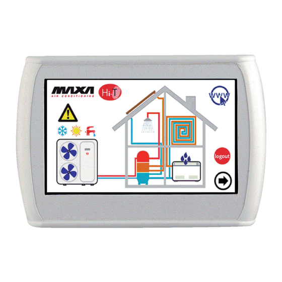
Hi‐T Centralized controller 3.3 START PAGE Figure 4. Start page. On Hi‐T start, while system loading, a splash screen appears with a logo. 3.4 HOME PAGE The home page has the following appearance: Figure 5. Home page – indication meanings. From the home page it is possible to access to the different device’s screens, simply touching the displayed resource. The sensible areas (indicated in the image by red boxes) inside this page are: 1. Heat pump/chiller (showing the working mode) 2. Status system and mode system display 3. Fan coil (with a status message of dehumidification active mode) 4. Display of any active alarms in the system 5. Information and location of the company 6. Name of the keyboard (access to information on the firmware version) 7. Configuring the Ethernet network 8. Log‐out (intermittent symbol if it’s active) 9. Arrow navigation, next page. ... - Page 10 Hi‐T Centralized controller Graphically, it also contains information on the presence or absence on the following utilities: 10. Tank 11. Radiant panels 12. Sanitary 13. Solar. On the main screen, in fact, it appears only utilities present and properly installed in the network or the active warnings at the time of viewing. If, for example, the network consists only of one or more chiller/heat pumps, without production of sanitary water and without storage, the screen shows graphically the presence of the chiller, but inside the house do not appear other object; in this case the appearance is the following: ...
-
Page 11: Chiller Screen/Heat Pump
Hi‐T Centralized controller In addition, directly on the home page, you can get the following information about the fan coils: • Presence of fan coils connected in a network, if the symbol appears (Figure 8. Fan coil network.); • Dehumidification fan coil operation, if the symbol of the drops appears (Figure 9. Fan coil dehumidification.). Figure 8. Fan coil network. Figure 9. Fan coil dehumidification. 3.4.1 CHILLER SCREEN/HEAT PUMP From the main page, by touching the symbol of the chiller (sensitive area number 1, Figure 5. Home page – indication meanings.), you can access to the chiller on network screen. From here you can access to the information related to the operations of the chiller; then you can uniquely identify each chiller present, assigning each a name. Figure 10. Chiller page – information and sensitive areas. ... - Page 12 Hi‐T Centralized controller 9. Icons of the navigation sidebar 3.4.1.1 ASSIGNMENT OF NAMES TO THE CHILLERS For the assignment of the name to a chiller, you must navigate between the pages of the chiller connected to the network until you get to the page of the chiller which you want to change the name: for apply this, you have to make single press into the pressure sensitive area 4. Once you find the chiller, press and hold for a few seconds in the same area 4. Then compose with the keyboard that appears the desired name. Figure 11. Insert chiller name. The name of the chiller can have a maximum of 13 characters. 3.4.1.2 CHILLER AREA The area 5 shown in Figure 10 gives indications about the operation (compressor running) of the chiller, graphically displaying the fan rotation. Pushing down on the area 5 you access to a further screen that shows a list of read data in real time related to the involved chiller: • Inlet water temperature (°C) • Outlet water temperature (°C) • Sanitary probe temperature (if it’s present and configured, °C). Accessing the same page with service or manufacturer access right (to enable the access right, press on the “configurations” icon present in the sensitive area 8 of Figure 10 and set the service/manufacturer password), the data displayed in real‐time are: • Inlet water temperature (°C) • Outlet water temperature (°C) • Sanitary probe temperature (if it’s present and configured) ...
- Page 13 Hi‐T Centralized controller 3.4.1.3 TOOLBAR CHILLER AREA On the left scroll sidebar there are icons that symbolize the active/activable functions in the chiller taken into account. In particular: Colourful icon = function enabled, Faded icon = function configured on the machine but not currently active. Below there is a table with icons that may appear in the scroll side bar. The presence or absence of the icon in the sidebar will be determined by the enable or disable of the function on the chiller. ORDER OF APPARANCE ICON FUNCTION 1 SANITARY HOT WATER 2 SANITARY INTEGRATION RESISTANCE 3 PLANT INTEGRATION RESISTANCE 4 BOILER ENABLING 5 DOUBLE SET‐POINT 6 DEHUMIDIFYING 7 ...
-
Page 14: Fancoil Page
Hi‐T Centralized controller 3.4.1.4 NAVIGATION AREA In the toolbar that appears at the right side of the chillers’ page, three icons are shown for the navigation between the pages: The first icon on the top allows you to return to the previous screen, the second allows you to enable maintainer/manufacturer access rights through a password to further information in real‐time, the last returns to the Home screen. The lower part shows date and time. If an icon appears transparent, it is not accessible. 3.4.2 FANCOIL PAGE From the main page, by touching the symbol of the fan coil (hot spot number 3, Figure 5), you enter the screen of the fan coils on the network. From here you can access the information related to the operation of the individual fan coil, identified by area of belonging and ... - Page 15 Hi‐T Centralized controller 7. Status and mode of operation related to a specific fan coil (with fan speed) 8. Active/activable functions (in the scroll bar on the left) Pressing the configuration symbol (Sensitive Area 4) leads to the setting of ventilation. The ventilation is changed for zones; hence changing the ventilation of a fan coil of a given area, the changes are applied to the entire area. The page for setting the ventilation looks like this: Figure 13. Ventilation speed configuration. The speed can be set are: • Minimum speed • Average speed • Maximum speed • Automatic regulation (auto‐mode) With the up and down arrows you choose the speed, with the green button you confirm the value set. 3.4.2.1 TOOLBAR OPERATION FANCOIL AREA In the left scroll sidebar there are icons that symbolize the active/activable functions in the fan coil zone considered. In particular: Colourful icon = function enabled, Faded icon = function unit configured but not currently active. Below there is a table with icons that may appear in the scroll side bar. The presence or absence of the icon in the sidebar will be determined by the enable or disable of the function which you refer on board the fan coil unit. ORDER OF APPARANCE ICON FUNCTION 1 WINDOW SWITCH ...
-
Page 16: Hi-T Area
Hi‐T Centralized controller 3.4.3 Hi‐T AREA Pressing in the sensitive area 6 of Figure 5, you have access to a screen showing the version and the date of release of the firmware installed. 3.4.4 ETHERNET CONNECTION CONFIGURATION Pressing in the sensitive area 7 of Figure 5, it appears the page: Figure 14. Ethernet network configuration page. On this page there are the addresses for the configuration of an Ethernet connection. Logging in with maintainer/manufacturer permission, you can change the default addresses. It’s implemented a local web server to access to the Hi‐T from local area network with a HTML 4.01 compatible browser (see Paragraph 5.2). ... -
Page 17: Second Main Page
Hi‐T Centralized controller 3.5 SECOND MAIN PAGE From the home page, touching the arrow icon to navigate to the next screen, you go to a second screen showing all of the detections carried out by the temperature sensors and humidity sensors in the system. Figure 15. Second Main page. Referring to the figure above: • Field 1 indicates the zone to which you are referring ; applying pressure on it, you switch to the next zone. ... -
Page 18: Home System
Hi‐T Centralized controller 3.6 HOME SYSTEM From the second page, touching the arrow icon to navigate to the next screen, you go to a third screen for general settings, the "system main page", showing the following functional icons: Figure 16. System main page. Above, from the left to right: 1) STATUS SETUP; 2) SET‐POINT SETUP; 3) PROGRAMS AND CHRONO‐THERMOSTAT. In the bottom, from the left to right: 4) SPECIAL FUNCTIONS; 5) CONFIGURATION; 6) HELP MENU. 3.6.1 STATUS SETUP PAGE Pressing the icon above, you access to the page: “Status setup”. Figure 17. “Status setup” page. Pushing on “System” you can set the status of the entire system, otherwise you can act on individual unit. 17 ... -
Page 19: Set-Point Setup Page
Hi‐T Centralized controller 3.6.2 SET‐POINT SETUP PAGE Pushing on the icon above, you access to the page: “Set‐point setup”. Figure 18. “Set‐point setup” page. From this screen you can set the chiller’ set and fan coil zones configured. If enabled, you can also set the sanitary hot water set (see Paragraph 4.6.2), the second set‐point (see Paragraph 4.9) and the offset for the climatic compensation(see Paragraph 4.10). 3.6.3 PROGRAMS PAGE (CHRONOTHERMOSTAT) Pushing on the icon above to access the page “Programs”. Figure 19. “Programs” page. From this page you can set the weekly program of chillers and fan coil zones separately. You can also program the legionella’s cycle and the production of hot water, if enabled (see Paragraph 4.6.5). ... -
Page 20: Special Functions Page
Hi‐T Centralized controller 3.6.4 SPECIAL FUNCTIONS PAGE Pressing the icon above to access the page "Special Functions" (see Paragraph 4.12). 3.6.5 CONFIGURATION PAGE Pushing on the icon above, you enter into the page "Configuration". Figure 20. “Configuration” page. From the configuration screen, you can access to the User‐Setup menu, to the service menu and to the manufacturer menu. Pushing on each of these items, it appears a numeric keypad for entering a password. Figure 21. Password entry. The user password is set by default to "0" (modifiable). 19 ... - Page 21 Hi‐T Centralized controller 3.6.5.1 USER MENU – KEYBOARD SETUP To access the user menu you have to set the user password (modifiable): 0. From here you can: • Set the date and the time by pressing on “Clock” (it appears the screen shown in Figure 22); • Set the language by pressing on “Language”; • Access to the setup of the keyboard, pressing on “Parameters”. Figure 22. Date and time page settings. It is possible to change the setup of the keyboard according to the parameters shown in the following table: N. PARAMETERS NAME UNIT DEFAULT VALUE MINIMUM VALUE MAXIMUM VALUE 1/3 User password Numb 0 0 999 2/3 Idle Backlight intensity % 5 0 100 3/3 Screensaver unlock Psw Numb 0 0 ...
- Page 22 Hi‐T Centralized controller 3.1.2. Chiller 02 3.1.3. Chiller xx 3.2. Keyboard 3.3. Fan coil 4. Alarm list The service’s parameters of the chiller correspond to those listed in the user‐installer manuals of the minichiller/heatpumps i‐ HWAK/WP V2/V2+ and of the chiller/heat pumps i‐HP. The service parameters of the keyboard are shown in the following table: N. PARAMETERS NAME UNIT ...
-
Page 23: Help Page
Hi‐T Centralized controller 41/44 Bitmap forcing icons Numb 0 0 4095 42/44 Dew‐point temp. margin °C 5.0 0.0 50.0 43/44 Min. staying time in dehumidification Seconds 300 0 600 44/44 Max. staying time in dehumidification Seconds 600 0 1200 Table 4. Keyboard menu service parameters. The fan coil service parameters are shown in the following table: N. PARAMETERS NAME UNIT DEFAULT VALUE MINIMUM VALUE MAXIMUM VALUE 1/9 Knob offset °C 0.0 ... -
Page 24: Status Machines And Functions
Hi‐T Centralized controller 4 STATUS MACHINES AND FUNCTIONS 4.1 NEWTORK MANAGEMENT The network which is headed by the remote control Hi‐T can be composed of a maximum of 7 chiller/heat pumps and up to 80 fan coils. For what concerns the configuration of the network, there are the following functions: • addressing procedure of fan coil; • automatic scanning of the network to discover devices; • radiant panel’s management (according to the set‐point). 4.2 REMOTE CONTROL CONNECTED WITH MORE CHILLER IN THE NETWORK In the each on‐board control panel, set the chiller (parameter H79) as described above . Then connect the chiller and the remote control Hi ‐T as shown in the drawing . In the remote control Hi‐ T, by setting the parameter Par 8/44 (Configuration‐ > Service Menu > Keyboard) related to the number of chillers in the network , you can configure the network: with Par 8/44 = 0 all the chiller in network feature a similar operation (parallel operation , according to a single set point) , while whit Par 8/44 ≠ 0 we have a decalibration on the steps of the chiller set ... -
Page 25: Chiller/Heat Pumps Managment
Hi‐T Centralized controller point, allowing a cascade operation. In particular, the parameters to be set in a network of the chiller to be configured in a cascade are: • Par 8/44: number of chillers in the network (for cascade operation); • Par 9/44: Rotation period (for cascade operation); • Par 10/44: (default 2.0 ° C): differential chiller (for cascade operation). In the case of cascade configuration (Par 8/44 ≠ 0), the set point of each chiller is changed by a multiple value of the parameter Par 10/44 (° C) (differential chiller), according to a step‐decalibration. After each period equal to Par 9/44 minutes, the priorities for the intervention of the chillers change, by rotating the decalibration of the set point of the chillers, in order to balance the load on the various machines. If a chiller is in alarm, it is excluded from the regulation. By default Par 8/44=0. 4.3 CHILLER/HEAT PUMPS MANAGMENT With the remote control Hi‐T, up to 7 MAXA chiller ( i‐HWAK V2/V2+ series and i‐HP series) will run. The main functions regulated are: • ON/OFF controlling; • Change of season (summer, winter, summer with sanitary mode, winter with sanitary mode, sanitary mode); • Set‐point setting; • Display current alarms; • Alarm history residing in the keyboard with the date and the time of the event; • Access to the parameters of the chiller (password protected); • Display of the main statuses of the chiller; • Weekly programming in summer, winter, sanitary mode and of the legionella disinfection cycle. 4.3.1 ENABLING THE INDIVIDUAL CHILLER FOR THE PRODUCTION OF SANITARY WATER Of all the chiller in the network enabled to produce sanitary water, you can choose using the appropriate sub‐menu in “Status ... -
Page 26: Scan Network
Hi‐T Centralized controller 4. Enter the service password and press on the mark’s confirmation; 5. Enter inside the “Addresses configuration”; 6. Enter inside the “Addresses assigns”; 7. Change the address with the arrows: the addresses can be assigned from the number 10; 8. Push on the confirmation icon next to the word “Start:”; 9. After a few seconds you will see "Set"; 10. Remove power supply from the first fan coil and power on the second; 11. Perform the same steps 7 through 9 for each fan coil units connected to the same keyboard. 12. It is important to assign to the fan coil units that will be bound to the same zone a series of consecutive addresses (e.g. whether there are 3 fan coil units within the same hall and if you want to associate them with a single thermal zone that we call HALL, you must give the themselves a series of addresses from 10 to 12, etc..). 4.5.2 SCAN NETWORK Once each fan coil has been addressed , it is essential to perform a network scan to check whether all the fan coils are correctly recognized. To do this: 1. restore power supply to all the fan coil; 2. enter to the service menu following the same procedure described in the previous section (points 2‐4) and enter "Scan network"; ... -
Page 27: On/Off Sanitary Mode
Hi‐T Centralized controller SYSTEM SUMMER WINTER OFF PROGRAMMED MANUAL MANUAL ECO OFF PROGRAMMED MANUAL MANUAL ECO With "Manual" and "Manual eco" the set‐point temperature set in the menu "Set water" and "Set water eco" is activated; they respectively ... - Page 28 Hi‐T Centralized controller 1. Enter the “Settings status”, then in “Sanitary mode”; 2. On the next screen select "All" to enable all the chiller to the production of sanitary water, or select only the chiller interested in this production (the other will be used exclusively for the plant); 3. Confirm by pressing the tick confirmation in the upper right area; Figure 23. Chiller choice for sanitary water. 4. In the "System" menu (system main page ‐> "Status setup" ‐> "System"), with the sanitary mode enabled by the parameter H10, it appears also the words "Winter and san", "Summer and san", "Sanitary" .
-
Page 29: Set-Point Setup
Hi‐T Centralized controller 4.6.3 SET‐POINT SETUP To manage the set point of the different zones and of the chiller is necessary: 1. from the system main page, go to "Set‐point setup"; 2. here you will find a list of the chillers and the areas previously assigned: • CHILLER • ZONE1 • ZONE2 • ………… 3. Select chiller or zone of consideration; 4. possible settings are "Winter", "Summer", "Sanitary" for the chiller, "Winter" and "Summer" for the fan coil zones: CHILLER CHILLER WINTER SUMMER SANITARY Water set eco Water set Sanitary set ... -
Page 30: Fan Setup
Hi‐T Centralized controller If enabled the double set‐point (from Home System ‐> Configuration ‐> Service Menu ‐> Parameters ‐> Chiller ‐> Chiller name ‐> H82: Enable second setpoint = 2, 3, or 4), (see Paragraph 4.9), the possible settings for the chiller are: DOUBLE SET‐POINT CHILLER WINTER SUMMER SANITARY Water set Water set eco Water set 2 Water set eco 2 Water set Water set eco Water set 2 Water set eco 2 Sanitary set Change the value of the set with the up and down arrows within the maximum and minimum limits indicated and confirm 4.6.4 FAN SETUP ... - Page 31 Hi‐T Centralized controller Figure 24. Chronothermostat, "Summer Chiller" page. 1. Scheduling of a day time‐line: • press on the day currently displayed to move to the next days and select a day; • choose if you want to set the way of operation in normal mode (press "Normal"), or Economy (press "Eco"), or if you want to set to Off (press "Off"); • check that after "Hour" appears the word "From" (if appears instead the word "To", you need to press it once to display the word "From") and select the hour and minute (the minimum allowable variation is 15 minutes)for the beginning of the time period; • press once on the "From" in a manner that appears the word "To" and select the hour and minute (the minimum variation permitted is 15 minutes) for the end of the time period; • confirm the single time period pressing the green symbol of confirmation ; • afterwards you can observe that, correspondingly to the selected time period, you will see a time‐line bar of the colour of the type of the selected set (if normal blue, green when in economy mode, no bar in "Off") ; • repeat the above steps for all the time slots that you want to set on that particular day. 2. It is possible to copy the programming for a particular day in another day; to do this: • select the day you want to copy the scheduling; • press the copy icon ; • select the day on which you want to copy the scheduling; • press the paste icon . ...
- Page 32 Hi‐T Centralized controller In the configuration pages on the chronothermostat colourful time‐lines appear: the blue time‐line indicates normal operation, the green time‐line indicates the economical operation, the red time‐line indicates the time in which the legionella cycle it is programmed (thus the machine in that condition may be active even if the scheduler is set to Off). 4.6.5.2 WEEKLY PROGRAMMING FAN COIL ZONE In a similar way to the scheduling of chillers, a weekly program of each zone can be set (independently between summer and winter), with minimum steps of 15 minutes. ...
-
Page 33: Keyboard Settings Procedure
Hi‐T Centralized controller Figure 27. Chronothermostat, "Legionella disinfection" page. The set timeline appears red‐colored. The pink line shows the eventual setting of the previous day that overruns in current day because the duration exceeds the midnight. 4.7 KEYBOARD SETTINGS PROCEDURE 4.7.1 SETTING OF THE LANGUAGE AND OF THE DATE/TIME To set the keyboard language: 1. from the system main page, go to “Configuration“ ; 2. then, go to “User menu” ; 3. -
Page 34: Fault Diagnostic
Hi‐T Centralized controller 4.8 FAULT DIAGNOSTIC 4.8.1 ACTIVE ALARMS You can view the current alarms of the connected units. To do this, from the home page, press the triangle icon of danger, if present; from here you can access to the list of all active alarms in the system. Also, when you are in an unit page (i.e. Chiller page, see Paragraph 3.4.1, and fan coil page, see Paragraph 3.4.2), by pressing the triangle that appears on the machine, you go to a menu where you can see current alarms of the selected machine. 4.8.2 ALARM HISTORY The keyboard manages a detected alarms list for all the plant that shows the date and time of the alarm, the affected machine and alarm type. In the historic are stored up to 100 alarms, once exceeded the limit, it automatically deletes the older alarms. ... -
Page 35: Measurement Of Temperature And Humidity
Hi‐T Centralized controller Note: If in the chiller is configured the presence of a digital input to the management of the second set point (chiller parameter H44 = 26, terminals SE‐SE, ref. Chiller manual), the management of the humidity control is not done from the remote control. The digital input is also possibly used for switch between the first and second set point during operation in winter mode. With double set‐point function enabled, if the chiller works on the second set‐point (radiant panels side), the double set‐point icon appears in the toolbar of the functions in the pages of chillers and fan coils and it remains transparent. If, however, the chiller switch to thermoregulate on the first set‐point (fan coil side), the double set‐point icon appears colourful. Similarly, the entry into dehumidification is marked in the function bar of chillers and fan coils by the transition from transparent icon to colourful icon. With parameters H82>1: FLOOR SIDE FUNCTION FAN COIL SIDE FUNCTION (2° SET‐POINT) (1° SET‐POINT) DOUBLE SET‐POINT ICON ICON DEHUMIDIFICATION if dehumidification is active Table 8. Double set‐point/dehumidification icon. In addition, in the home page, you will see a visual indication of activation of the fan coil dehumidification see Figure 9. Fan coil dehumidification. ). 4.9.1 MEASUREMENT OF TEMPERATURE AND HUMIDITY The ambient temperature and the relative humidity measured by the sensors built into the Hi‐T remote control, are available to the chiller, which can then use these values measured for their regulators, where required. 4.9.2 DEW POINT AND DEHUMIDUFUCATION CONTROL Given the environmental temperature and the humidity, the Hi‐T remote control calculates the dew point. ... -
Page 36: Climatic Compensation
Hi‐T Centralized controller 4.10 CLIMATIC COMPENSATION It is possible to compensate the set‐point according to outdoor temperature, in a different way between heating and cooling modes, first and second set‐point. In such a case be sure that the b08 parameter (System main page ‐> Configuration ‐> Service menu ‐> Parameters ‐> Chiller ‐> Chiller name ‐> b08: Enab. dynamic set point) is disabled (=0) on the chiller. Setpoint Setpoint Offset Offset Offset Offset T ext T ext Set Text Set Text Figure 29. Climatic compensation. • Set = T water, T water ECO o T water, T water ECO, settable from the page: ”Set‐point setup” ‐> “Chiller”. • Offset = offset settable from the page: ”Set‐point setup” ‐> “Chiller” (the variable “Offset” appears only if the “m” coefficients have been configured). ... -
Page 37: Screed Function
Hi‐T Centralized controller Figure 30. Page "Special functions". The available functions are described in the following paragraphs. 4.12.1 SCREED FUNCTION By pressing the icon related to the screed function you access to a new menu in which you can choose which units should be enabled to this function: Figure 31. Chiller multiple choice, screed function. Once you choose the chillers which participate to this regulation, the system has the following behaviour: • All the heat pumps enabled in the screed function are forced to heat mode. • All the heat pumps not enabled in the screed function are forced to off mode. • The heat pumps set‐point is given by the parameter “Screed function set”, which can be set among the service parameters (Configuration ‐> Service menu ‐> Keyboard ‐> Par 36/44: ” Screed function Set”). • The function has a duration given by the service parameter: Configuration ‐> Service menu ‐> Keyboard ‐> Par 37/44: ” Duration screed function”. After such period the system returns to the previous settings. ... -
Page 38: Remote Access
Hi‐T Centralized controller The manufacturer’s password can be modified by accessing to manufacturer’s parameters (see Paragraph 3.6.5.3). Once the password has been inserted, is allowed the full navigation in all the pages in which the access has been granted. Once the navigation has terminated, log‐out should be done by a touch on the related symbol which is flashing in the low‐right side of the home page. The log‐out happens automatically after 5 minutes of touch‐screen inactivity or after 20 minutes from the access to the current level of protection. These timing values can be modified from service or manufacturer’s parameter. There is a password to unlock the screensaver, set by default to “0” and modifiable by accessing to user’s parameters (see Paragraph 3.6.5.1). 5 REMOTE ACCESS ... - Page 39 Hi‐T Centralized controller Figure 32. Hi‐T Ethernet main page. The indication on Status, Season and Alarms is related to the entire system. The room temperature and the relative humidity are the ones measured from the sensors integrated inside the current Hi‐T. To shift to next available pages, click on the links at the page bottom. Figure 33. Hi‐T Ethernet "Command" page. The commands present in the “Command” page are referred to the entire system. Once sent the commands, a confirmation page appears. ...
- Page 40 Hi‐T Centralized controller Figure 34. Command sent confirmation page. Figure 35. Hi‐T Ethernet "Set‐point” page. In the “Set‐point” page are available, in read only mode, the set‐point set by Hi‐T. 39 ...
- Page 41 Hi‐T Centralized controller Figure 36. Hi‐T Ethernet “Alarms” page. The “Alarms” page is related to all the active alarms inside the system at the moment when the page is shown. ...
-
Page 42: Firmware Update
Hi‐T Centralized controller 6 FIRMWARE UPDATE In the home page, by pressing on the symbol in the left‐high side, showing Hi‐T, it is possible to see the current firmware version installed in the touch‐screen. In case of firmware update, it is possible to make the upgrade by means of an USB key, using the on‐board USB port. For the upgrade: ‐ copy the upgrade file in the main root of a USB pen‐drive; ‐ insert the pen‐drive into the Hi‐T USB port; ‐ enter into “Configurations ‐> “User’s menu” (see Paragraph 3.6.5.1); ‐ after having inserted the user’s password and entered into “User’s menu”, select the string which appears “Firmware update”; ‐ the controller automatically recognizes the firmware presence inside the USB pen‐drive and starts the updating procedure; ... -
Page 43: Hns System Description
Hi‐T Centralized controller 7 HNS SYSTEM DESCRIPTION The HNS system can be coupled only with the following hydronic units: • HWF/HWI fan coils; • LWF/LWI fan coils; • HCA/B and HCA/4B hydronic cassette types; • HCN ducted types. NOTE: the installation with the MI wall mounted types is not possible. There are 2 ways to install an HNSbox system: 1) Purchase of the DRAL‐NET and the SB modules separately and subsequent installation on the unit at customer’s expenses. In this case, it is possible to install the DRAL‐NET control on the wall in order to make accessible the temperature’s knob, which allows an adjusting of the same within a prefixed control set by the Hi‐T. For example, supposing the ambient temperature set at 20°C (via Hi‐ T), it is possible, by means of the DRAL‐NET’s knob, to adjust the set within a given temperature range, such as +/‐5°C, +/‐6°C (adjusting by parameter), and the like. In this case, the whole installation’s procedure is at the installer’s expenses. By and large, the ... - Page 44 Hi‐T Centralized controller • until n° 7 cascade chillers with terminal units not connected • n°1 chiller with connected terminal units (until n° 80 terminal units) • until n° 7 cascade chillers with terminal units connected (until n° 80 terminal units) The chillers connected in series do not need further working probes to be placed onto the system total discharge piping as the centralized system acquires the single temperature of every unit and “thermal‐regulates” as per the average discharge temperature. The advantage of a combined HNS system is mainly based on the fact that the user has the Hi‐T panel as the sole ...
-
Page 45: The Hnsbox
Hi‐T Centralized controller 8 The HNSbox 8.1 FUNCTIONS The HNSbox has been conceived to get the greatest flexibility and adaptability as for the connection among the hydronic units and the HYDRONIC NET SYSTEM managing system. Find below the connecting logic layout of the HNS system components: 8.2 HNSbox DESCRITPION The HNSbox is made up of the following components: • DRAL‐NET, control; • SB, serial adaptor; • 2.5 mm terminal board (“Mammut” model type); • IP56 Gewiss 44207 box; • Power cables; • Signal cables. WARNING: The connections described in the wiring diagrams (power and signal connections) of this manual ... -
Page 46: Connecting The H I -Tkeyboard, The Chiller And The Hydronic Units
Hi‐T Centralized controller 8.3 CONNECTING THE Hi‐T KEYBOARD, THE CHILLER AND THE HYDRONIC UNITS 45 ... -
Page 47: Dip Switches Setting
Hi‐T Centralized controller DIP SWITCHES SETTING Modify the Dip Switches inside the DRA‐L NET control as per: • Installed unit; • Water unit installation position; • Operation logic. Dip Switches functions: Dip Switch no. ON OFF Description x Floor unit 1 x Ceiling unit x On demand ventilation (1) 2 x Continuous ventilation (2) x Valve thermal regulation 3 x ... -
Page 48: Air Sensor
Hi‐T Centralized controller 8.6 AIR SENSOR Install the air sensor in the unit’s finned battery inlet opening, and fix it by means of an electrical type clamp. 47 ... -
Page 49: Wirings
Hi‐T Centralized controller 8.7 WIRINGS Hydronic cassettes type: See the user – installer manual to get information as for the cassettes type wiring diagrams. HCA/B Picture 1. HNSbox connection with HCA/B. ... - Page 50 Hi‐T Centralized controller HCA 4/B 2 4 V A C S T 1 °C K A1 K A 1 Q F1 R D1 230V 50Hz H CA /4B 22-120 HNSbox terminal board R S 48 5 As for the RS485 terminal board, see the “signal wiring connection” section. The dashed lines show the connections to be carried out by the installer.
- Page 51 Hi‐T Centralized controller Ducted type: See the user – installer manual to get information as for the ducted type wiring diagrams. HCN09 HNS box N = neu tral L = line Air sensor grou nd 23 0V 50 H z Water sensor Window contact Black=Hight sp eed Blue=M edium spe ed Re d=Low speed W hite=Neutral m in.
- Page 52 Hi‐T Centralized controller HCN09 with SBE module 400V /3+N /50Hz HNS box Air sensor KMR1 Water sensor Window contact m in. speed E LE C TR IC A L H E ATIN G S EC TIO N B O AR D m ed.
- Page 53 Hi‐T Centralized controller HCN13÷43 HNS box N = Neu tra l L = Lin e Air sensor 230 V 50 H z Water sensor Window contact W hite = Com mon Red = Low speed Blue = Medium speed min. speed Black = Hight speed Yellow-Green = Ground med.
- Page 54 Hi‐T Centralized controller HCN13÷43 with SBE module P ow er supply 400 / 3+ N / 50-60H z W h ite = C o m m o n R e d = L o w s p e e d B lu e = M e d iu m s p e e d HNS box B la c k = H ig h t s p e e d...
- Page 56 37040 Arcole Verona - Italy Tel. +39 - 045.76.36.585 r.a. Fax +39 - 045.76.36.551 r.a. www.maxa.it e-mail: info@advantixspa.it The data indicated in this manual is purely indicative. The ma- nufacturer reserves the right to modify the data whenever it is...
Need help?
Do you have a question about the HI-T and is the answer not in the manual?
Questions and answers