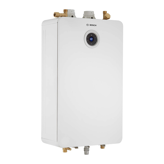
Bosch Greentherm T9900 SE 160 Installation And Operating Instructions Manual

Bosch Greentherm T9900 SE 160 Installation And Operating Instructions Manual

Indoor residential tankless water heaters, 160 000/199 000 btu- natural gas 160 000/199 000 btu - liquefied petroleum lp gas
Hide thumbs Also See for Greentherm T9900 SE 160:
Table of Contents

Advertisement

Installation and Operating Instructions
INDOOR RESIDENTIAL TANKLESS WATER HEATERS
Greentherm T9900 SE 160/199 | i 199
160 000/199 000 Btu- Natural Gas | 160 000/199 000 Btu - Liquefied Petroleum
(LP) Gas
WARNING!
Improper installation, adjustment, alteration, service or maintenance can cause
injury or property damage. Refer to this manual. For assistance or additional infor-
mation consult a qualified installer, service agency or the gas supplier.
NOTICE
Upon completion of the installation, these instructions should be handed to the user
of the appliance for future reference.

Advertisement

Table of Contents
loading

Summary of Contents for Bosch Greentherm T9900 SE 160

  • Page 1 Installation and Operating Instructions INDOOR RESIDENTIAL TANKLESS WATER HEATERS Greentherm T9900 SE 160/199 | i 199 160 000/199 000 Btu- Natural Gas | 160 000/199 000 Btu - Liquefied Petroleum (LP) Gas WARNING! Improper installation, adjustment, alteration, service or maintenance can cause injury or property damage.
  • Page 2: Table Of Contents

    Table of contents 6.5 Information /Adjustments menu ....47 Table of contents 6.5.1 “P4” - Information ......47 6.5.2 SA - Settings .
  • Page 3: Key To Symbols And Safety Instructions

    Key to symbols and safety instructions Safety instructions Key to symbols and safety instructions H DANGER: Key to symbols Before installation, Warnings ▶ Read all instructions before installing. In warnings, signal words at the beginning of a warning are used Perform the steps in the indicated to indicate the type and seriousness of the ensuing risk if measures for minimising danger are not taken.
  • Page 4 Key to symbols and safety instructions H WARNING: ▶ Inform the certified installer who installed the appliance to change ▶ To ensure that the water heater appliance installation location. functions properly, follow these installation and maintenance H DANGER: instructions. Risk of poisoning! ▶...
  • Page 5 ▶ Immediately correct all faults to highest risk of being scalded. Never prevent system damage. leave such individuals in the tub or ▶ Use only Bosch spare parts! shower unattended under any H CAUTION: circumstances. Children must not be Instruct the customer allowed to operate hot water faucets ▶...
  • Page 6 Key to symbols and safety instructions ▶ If the building has occupants in the ▶ When installation of the water heater above groups who operate hot water is complete, inspect and confirm faucets, or state laws / local proper ground conductor. ordinances stipulate specific water H CAUTION: temperatures, take the following...
  • Page 7 Key to symbols and safety instructions NOTICE: DANGER: Fatal accidents! ▶ The appliance should be located in an area where leakage of the heater or connections will not result in damage to the Carbon monoxide poisoning. area adjacent to the appliance or to lower floors of the ▶...
  • Page 8: Safety Information

    Safety information NOTICE: Safety information Appliance damage! ▶ Label all wires prior to disconnection when servicing controls. Wiring errors can result in improper and dangerous operation. Verify proper operation after servicing. WARNING: Relief valve discharges! ▶ If a relief valve discharges periodically, this may be due to thermal expansion in a closed water supply system.
  • Page 9: Appliance Details

    For more information go to www.P65Warnings.ca.gov. Accessories (Bosch part #) • Neutralizer Kit (7738001483) BOSCH water heater complies with the State of California Lead • Wi-Fi module [802.11 b/g/n (2.4 GHz)] (7736504944) Law (AB1953). •...
  • Page 10: Specifications (Technical Data)

    Appliance details Specifications (Technical data) Approved in US/Canada Technical characteristics Units Greentherm T9900 SE/i Greentherm T9900 SE 199 000 Btu 160 000 Btu Capacity Maximum flow rate at a 35 °F (19.4 °C) rise GPM (l/min) 11.2 (42.4) 9 (34) Maximum flow rate at a 45 °F (25 °C) rise GPM (l/min) 8.7 (32.9)
  • Page 11 Appliance details Technical characteristics Units Greentherm T9900 SE/i Greentherm T9900 SE 199 000 Btu 160 000 Btu Net weight pounds (kg) 78.70 (35.7) / 81.13 (36.8) 74.3 (33.7) Gross weight pounds (kg) 91.05 (41.3) / 93.48 (42.4) 86.64 (39.3) Electrical Nominal V AC Frequency...
  • Page 12: Unpacking The Heater

    Gas - Propane or Natural Gas. Identification labels are found Please consult Bosch for further details to determine if this will on the shipping box, and on the rating plate which is located on function in your application.
  • Page 13: General Rules To Follow For Safe Operation

    Appliance details 2. Carefully plan where you install the ▶ Slowly open the front cover [1]. heater. Correct combustion air supply and vent pipe installation are very important. If not installed correctly, fatal accidents can occur, such as carbon monoxide poisoning or fire. 3.
  • Page 14 Appliance details 6. Keep the water heater area clear and free from combustibles and flammable liquids. Do not locate the heater over any material which might burn. 7. Correct gas pressure is critical for the proper operation of this heater. Gas piping must be sized to provide the required pressure at the maximum output of the heater, while all the...
  • Page 15: Dimensions And Minimum Installation

    Appliance details Dimensions and minimum installation clearances Fig. 5 Dimensions Greentherm T9900 SE/i – 6 720 813 635 (2019/03)
  • Page 16: Installation Instructions

    ▶ The water heater must be installed by a qualified installer in accordance with these instructions. If improperly installed, a hazardous condition such as explosion or carbon monoxide poisoning could result. Bosch Thermotechnology Corp. is not responsible for improperly installed appliances.
  • Page 17: Heater Placement And Clearances

    Installation instructions NOTICE: WARNING: Risk of appliance freezing! ▶ Flammable materials, gasoline, pressurized containers, or ▶ In areas where outside temperature is routinely below 32°F any other items or articles that are potential fire hazards (0 °C) and the heater is to be installed on the inside of an must NOT be placed on or adjacent to the heater.
  • Page 18: Venting

    Installation instructions CAUTION: Personal injury and property damage. ▶ Appliance must be installed vertically. Venting DANGER: ▶ Do not reduce the exhaust or combustion air vent pipe sizes. ▶ Do not common vent with any other vented appliance or stove. ▶...
  • Page 19 Installation instructions Flue temperature: ▶ To prevent the risk of flue material overheat the appliance's flue temperature is sensed and is limited. The flue temperature limit is depending on inlet water temperature. ▶ Residential models: Maximum flue temperature is limited to 145 °F (63 °C).
  • Page 20 Installation instructions 4.6.2 Approved vent components and terminations Bosch 196050 2" Bird screen 196051 3" Bird screen 196052 4" Bird screen h 2.5 2", 3", and 4" SCH40 (Solid Core) PVC/CPVC 45° long sweep elbow h 2.5 2", 3", and 4" SCH40 (Solid Core) PVC/CPVC 45°...
  • Page 21 Installation instructions IPEX 196984 2" PVC Low profile termination kit Exhaust: 0 196985 3" PVC Low profile termination kit Intake: 5 196986 4" PVC Low profile termination kit IPEX 081216 2" PVC Wall Termination Kit Exhaust: 081219 3" PVC Wall Termination Kit Intake: 7.5 Temple ECAP 321...
  • Page 22 Installation instructions h Exhaust: Duravent 810009692 (2" x 4") Black PP Vertical Termination Kit - Concentric M&G 810009720 (3" x 5") Black PP Vertical Termination Kit - Concentric 810009693 (2" x 4") Terra-Cotta PP Vertical Termination Kit - Concentric Intake: 40 810009721 (3"...
  • Page 23 Installation instructions 4.6.3 Vent specifications Establish vent clearances that comply with the vent manufacturer's specifications and all applicable national/local Improper gas pressure or vent length may result in undesired codes. symptoms or errors such as noisy burner, C1, C2, CF, EA, EC. Minimum combustion air and exhaust pipe length The vent for this appliance shall not terminate: The minimum exhaust pipe length is 1 ft (0.3m) of straight vent...
  • Page 24 Installation instructions Required direct vent terminal clearances (twin pipe / concentric penetration) Fig. 10 Canadian installations U.S. installations with direct vent terminals with direct vent A Clearance above grade, veranda, porch, deck or balcony 12 in. (30cm) 12 in. (30cm) B Clearance to window or door that may be opened 36 in.
  • Page 25 Installation instructions 3) A vent shall not terminate directly above a sidewalk or paved driveway that is located between two single family dwellings and serves both dwellings. 4) Permitted only if veranda, porch, deck or balcony is fully open on a minimum of two sides beneath the floor. Table 9 Clearance in accordance with local installation codes and the requirements of the gas supplier.
  • Page 26 Installation instructions Required other than direct vent terminal clearances (single pipe penetration) Fig. 11 Canadian installations U.S. installations with with non direct vent non direct vent terminals A Clearance above grade, veranda, porch, deck or balcony. 12 in. (30cm) 12 in. (30cm) B Clearance to window or door that may be opened.
  • Page 27 Installation instructions 3) A vent shall not terminate directly above a sidewalk or paved driveway that is located between two single family dwellings and serves both dwellings. 4) Permitted only if veranda, porch, deck or balcony is fully open on a minimum of two sides beneath the floor. Table 10 "...
  • Page 28 This situation will pull cold air through the heat exchanger and can lead to damage and a water leak and is not covered by the product's warranty. In the event of negative air pressure causing back drafting contact Bosch for information. Fig. 13...
  • Page 29 Installation instructions Fig. 16 Horizontal venting system (sealed combustion) [1] Intake Fig. 15 Horizontal venting installation air intake piping not [2] Exhaust shown) [1] Termination [2] Water heater [3] Elbow [4] Horizontal run should slope ¼" per foot upwards to water heater [LA] 12 inches (305 mm) (18 in.
  • Page 30 Installation instructions With Flex Pipe the maximum length is reduced by 60%, (applies only to the section in flex PP). Example: 10 feet of flex PP is equivalent to 25 feet of rigid PP. Flex Pipe according to the suppliers instructions for use in the vertical part of the installation only.
  • Page 31 Installation instructions Refer to fig. 23 for preferred installation positions in the vent NOTICE: system. Installation considerations: ▶ Install the damper per the supplied manufacturer‘s A blocked breather may cause an undesired double-siphon instructions. effect. The damper is only to be used in the exhaust vent piping. ▶...
  • Page 32: Factory Regulation

    Installation instructions 4.6.7 Single Pipe Venting • Appliances located in confined spaces: The confined space must be provided with two permanent NOTICE: openings, one commencing within 12 inches (304.8mm) of the top and one commencing within 12 inches (304.8mm) of the bottom of the enclosure. Each opening ▶...
  • Page 33: Gas Piping & Connections

    Installation instructions ▶ Tighten gas pipe with the support of a wrench, see fig. 24. WARNING: ▶ The gas type conversion must only be carried out by a qualified contractor. Gas piping & connections Before connecting the gas supply, be sure that the heater is set for the same gas to which it will be connected.
  • Page 34 Installation instructions GAS LINE SIZING The gas supply piping for a single heater should be sized for a maximum draw of 199000 BTU/hr for Greentherm T9900 SE/i. Measure the length of the gas supply line from the building's gas main to the heater and use the chapter 4.8.1 and 4.8.2 or the gas line manufacturer’s sizing tables to determine the pipe diameter necessary.
  • Page 35 Installation instructions 4.8.2 Gas Line Sizing Tables for LP GAS For your convenience, see below an excerpt from gas line sizing tables for a single LP appliance. Their intended use is for pipe sizing between the 2nd stage (low pressure) regulator and the appliance. For details, see the current NFPA 54 or NFPA 58. Required input for 160000 / 199000 BTU/hr for the Greentherm T9900 SE/i.
  • Page 36: Water Quality

    Connecting the pressure relief valve (PRV) the values specified in fig. 26 (grey area), Bosch recommends A pressure relief valve is included in the box and must be consulting a local water treatment professional for water installed at the time of installation.
  • Page 37 Installation instructions NOTICE: ▶ This heater is not approved for preheated water applications exceeding 140 °F (60 °C) for Residential appliances, in these cases use a 3-way valve or mixing valve must be installed before the appliance to prevent water exceeding 140 °F (60 °C) for Residential appliances from entering the appliance.
  • Page 38: Domestic Hot Water Recirculation

    Installation instructions 4.11 Domestic hot water recirculation The following drawings are provided to illustrate two possible recirculation designs. These schematic is for illustration only and must not be used for actual Installation without appropriate engineering and technical advice from a properly licensed professional in the locality where the installation is made.
  • Page 39: Space Heating Applications

    • External NTC - 7 736 504 583 – Only compatible with Bosch cable/sensor accessory (7736504583). Sensor must be inserted into the tank pocket and plug in at the tank connector in bottom of the appliance.
  • Page 40 ▶ The use of a flow switch is recommended to ensure DHW priority and to prevent “cold-blow” situations when the Bosch tankless water heater is used with an air handler. Air handler installation must include a pump. The flow switch should be used to disable the blower on the air-handling system when domestic water is used.
  • Page 41 [14] Air handler [2] Cold water inlet [15] Shutoff valve (field supplied) [3] Pressure relief valve [16] NTC sensor (Bosch accessory) [4] Gas supply [5] Shut off gas valve (field supplied) [6] Thermal expansion tank (as required) [7] Air purge (field supplied)
  • Page 42 Installation instructions Fig. 34 Pressure drop curve Greentherm T9900 SE/i – 6 720 813 635 (2019/03)
  • Page 43: Measuring Gas Pressure

    Electrical connections 4.13 Measuring gas pressure 4.13.1 Gas supply pressure Confirm gas pressure upon installation. Connecting manometer ▶ Shut off gas supply at installer supplied shutoff valve for Fig. 35 Gas pressure test port this water heater. [1] Gas pressure measuring port ▶...
  • Page 44: Position Of The Fuses In Control Unit

    Operation instructions ▶ Check the fuse in the printed circuit board, for electrical continuity, see fig. 38, [1]. Fig. 36 Connecting power supply cord [1] Power cord length: 5.9 ft (1.8m). Fig. 38 Fuse position Note: The power supply that the appliance is plugged into [1] Fuse should be isolated from possible water damage.
  • Page 45: For Your Safety Read Before Operating Your

    Operation instructions For your safety read before operating your ▶ Touch and hold symbol for more than 3 sec. The LCD display shows the selected temperature. water heater When the burner is on, the display shows symbol (Fig. 39, [7]). WARNING: Explosion hazard! ▶...
  • Page 46: Programming The Default Setpoint

    Operation instructions 6.4.1 Programming the default setpoint temperature To increase setpoint temperature limit of the appliance, ▶ Access the menu LM - Temperature Limited ( Section 6.6) and select Unlocked. A lower temperature set point will reduce the risk of scolding, reduce energy consumption and increase the longevity of the heat exchanger.
  • Page 47: Information /Adjustments Menu

    Operation instructions Information /Adjustments menu • Operation Hours - number of hours burner has been operating. Access to Information / Adjustments menu OD Operation Data Display shows the set point temperature. Allows you to view various parameters of the current operation ▶...
  • Page 48 Operation instructions ▶ Touch the symbol when month is correct. ▶ Use the symbols to set the day. ▶ Touch the symbol when the day is correct. ▶ Use the symbols to set the year. ▶ Touch the symbol when the year is correct. ▶...
  • Page 49 Operation instructions ▶ Use the symbols to select the day of the week ▶ Touch the symbol when month is correct. to be copied. ▶ Use the symbols to set the day. ▶ Use the symbols to choose option Copy to. ▶...
  • Page 50: Au - Technical Settings

    Operation instructions ▶ Use the symbols to select A8 Startup Delay. ▶ Touch the symbol after reaching the desired value. The time is defined, the brightness value must now be ▶ Touch the symbol programmed. Display shows Startup Value(s). ▶ Use the symbols to set the brightness of the ▶...
  • Page 51: Service Menu - Au Technical Settings

    Operation instructions ▶ Touch the symbol until the display shows P9 Purge. RS Recirculation Settings After 2 sec. the fan starts working to purge the exhaust To define recirculation comfort level, circuit. ▶ Touch the symbol ▶ Touch symbols to define comfort level. –...
  • Page 52: Water Valves Calibration

    Operation instructions ML Model ▶ Touch symbol OK. ▶ Touch the symbol ▶ Touch symbols to select MF main valve. Display shows appliance model. ▶ Touch symbol OK. – Indoor The appliance will start the auto calibration of main valve. ▶...
  • Page 53 Operation instructions ▶ Touch the symbol Display blinks 3 times and return to P7 menu. 6.8.1 Gas conversion from NG to LPG WARNING: Fatal accidents! Before any service or testing in the appliance, ▶ Turn off the appliance. ▶ Disconnect the power supply cord. ▶...
  • Page 54: Wi-Fi Connection

    Before activating Wi-Fi module, ▶ Unplug the appliance from the power supply. ▶ Download the “Bosch Water” app, available for Android and IOS for communication with the water heater, see fig. 51. ▶ Open the app and follow the instructions.
  • Page 55 HT Hotspot option is defined. ▶ Download the “Bosch Water” app, available for Android and ST Status IOS for communication with the water heater, see fig. 51. Display shows the status of wireless connection: •...
  • Page 56: Maintenance And Service

    Maintenance and service ▶ Touch the symbol Maintenance and service A green check mark is displayed indicating that reset is complete. DANGER: 6.9.3 Problem solving to activate Wi-Fi Exceed Wi-Fi activation time ▶ Always shut off the electrical power supply, shut off the The Wi-Fi module must be activated within 15 minutes after manual gas valve and shut off the water valves whenever plug in the appliance to the power supply.
  • Page 57: Required Annual Maintenance

    Maintenance and service Required annual maintenance Winterizing for seasonal use (To remove front cover, see page 12) The water heater must not be installed in a location where it may be exposed to freezing temperatures unless connected to electrical power. All water must be drained from the heater in WARNING: order to avoid damage to the unit from exposure to freezing temperatures.
  • Page 58: Troubleshooting

    Troubleshooting ▶ Connect a line (A) from the outlet of the circulating pump ▶ Reconnect the electrical supply to the unit, open the water (installer supplied) to the inlet drain connection on the shutoff valves, and return the unit to service. water heater (see fig.
  • Page 59: Burner Does Not Ignite When A Hot Water Faucet Is Opened

    Troubleshooting Burner does not ignite when a hot water 2. Confirm the heater's gas type coincides with the type of gas being supplied. See fig. 2, page 12 for location of rating faucet is opened plate. It is recommended to use “P4 Information” page 47, chapter 6.5.1 as a tool for problem solving.
  • Page 60: Hot Water Temperature Fluctuates At Tap

    Troubleshooting Hot water temperature fluctuates at tap 3. Ensure that the venting used is according to specifications (see section 4.6) and cross contamination does not exist. 1. If the water heater set point temperature is high, mixing at Ensure that intake and exhaust terminations maintain the faucet could deactivate the water heater.
  • Page 61: Manifold Gas Pressure

    Troubleshooting 2. How to verify the recirculation flow. Close all water taps, ▶ Loosen the set screw of the pressure head point [B]. access to information menu, P4 information > Operation ▶ Connect the pressure gauge connection "+" to the test Data, choose the option Flow.
  • Page 62 In case of positive results for all these actions: ▶ Perform manual adjustment according to chapter 8.12.2 or contact Bosch support line for further assistance. Fig. 56 Auto Adjustment Greentherm T9900 SE/i – 6 720 813 635 (2019/03)
  • Page 63 Troubleshooting 8.12.2 Manual Gas and Air Adjustment ▶ Change L1 Gas Adjust parameter until reaches 100% ± 2% Gas and Air adjustment is also possible to perform manually. ▶ Increase L1 Gas Adjust parameter to increase output This is only recommended if the automatic adjustment process power, and vice-versa.
  • Page 64 Troubleshooting B1 Internal Adjust ▶ Increase L2 Gas Adjust parameter to increase ION value and vice-versa. ▶ Touch symbols until display shows B1 Internal Adjust. L2 Gas Adjust 6720816815-39.1V Fig. 62 B1 Internal Adjust - P1 Active Fig. 64 L2 Gas Adjust - ION value ▶...
  • Page 65: Co Emissions Check

    Default setting is Off. are available for certification purposes and advanced ▶ Only a qualified technician can change this parameter. troubleshooting with guidance from BOSCH support line. For optimal operation, use the default settings. 8.13 CO emissions check Ionization Control In case air/gas combustion adjustment has been performed check emissions using reference values in tables 27 and 28.
  • Page 66 Troubleshooting ▶ Insert analyzer probe into the measuring port. The tip of the range (%) Max. CO level probe should be in the center of the flue pipe (approx 1.5" (measured) inserted). Avoid air gaps between probe and measuring Greentherm 9800 SE port as they can alter readings.
  • Page 67: Problem Solving

    Problem solving Problem solving Error code diagnostics Installation, maintenance and repair must only be carried out by qualified contractors. The following table describes the To remove error codes from the display, solutions for possible problems. ▶ Touch the On/Off button more than 3 sec. (long press). Display Description Solution...
  • Page 68 Problem solving Display Description Solution Condensing unit flue gases temperature [16] ▶ Descale appliance ( section 7.3). above 392 °F (200 °C) and/or flue gases temperature [15] above 145 °F (63 °C) at the exhaust sensor [15]. Appliance regulates power to protect against overheating.
  • Page 69 Problem solving Display Description Solution Flue blockage detected during operation due to ▶ Reset error (touch and hold on/off button for 3 excessive pressure on the siphon. seconds). If the problem persists: ▶ Check exhaust pipes and terminals for obstructions and reset the error.
  • Page 70 Problem solving Display Description Solution Electronic control unit internal error. ▶ Reset error (touch and hold on/off button for 3 seconds). If the problem persists: ▶ Replace electronic control unit. Error during ionization test. Electronic control unit ▶ Replace electronic control unit. internal error.
  • Page 71 Problem solving Display Description Solution Gas leakage in the gas path (gas valve or gas ▶ Replace the gas valve and/or gas manifold. manifold shut-off valves). ▶ After gas valve and/or gas manifold replacement perform gas and air tuning ( section 8.12). Touch screen key pressed for more than 20 ▶...
  • Page 72: Electrical Diagram

    Electrical diagram Electrical diagram Fig. 66 Electrical diagram Greentherm T9900 SE/i – 6 720 813 635 (2019/03)
  • Page 73 Electrical diagram [1] Ionization sensor [2] Fan [3] Ignition electrode [4] Power supply [5] Connection for anti freeze kit [6] Connection for recirculation pump [7] Connection for remote control [8] Gas valve - Modulation [9] Water bypass valve [10] Electrovalve 3 [11] Electrovalve 1 [12] Electrovalve 2 [13] Gas valve - Solenoide safety...
  • Page 74: Sensor Resistance Charts

    Sensor resistance charts Sensor resistance charts RESISTANCE (KOHM) 6720816948-40.1V Fig. 67 Inlet, outlet and heat exchanger water temperature sensors characteristics 0.01 RESISTANCE (KOHM) 6720816948-41.1V Fig. 68 Flue gases and condensing unit flue gases temperature sensors characteristics Greentherm T9900 SE/i – 6 720 813 635 (2019/03)
  • Page 75: Interior Components Diagram

    Interior components diagram Interior components diagram 12.1 Interior components 6720813635-24.2V Fig. 69 Interior components [1] Inlet water filter [12] Condensate trap [2] Air fan [13] By-pass water valve [3] Control unit [14] Ionization sensor [4] Gas manifold [15] Ignition electrodes [5] Burner [16] PRV connection [6] Heat exchanger...
  • Page 76: Protecting The Environment

    Protecting the environment Protecting the environment Installer Checklist to be completed by installer upon installation Packing The packing box may be fully recycled as confirmed by the recycling symbol Components Serial Number ___ ___ ___ ___ ___ ___ ___ ___ Many parts in the heater can be fully recycled in the end of the product life.
  • Page 77: List Of Used Open Source Components

    List of used Open Source Components List of used Open Source Components The following open source software (OSS) components are included in this product: Name of OSS Version of OSS Name and Version of License (License text More Information Component Component can be found in Appendix below) Arphic Technology...
  • Page 78 List of used Open Source Components parties remain in full compliance. DIRECT, INDIRECT, CONSEQUENTIAL, INCIDENTAL, SPECIAL Acceptance OR EXEMPLARY DAMAGES ARISING OUT OF THE USE OR You are not required to accept this License, since you have not INABILITY TO USE THE FONT (INCLUDING BUT NOT LIMITED signed it.
  • Page 79 List of used Open Source Components unmodified copies of the Font Software, subject to the following conditions: 1. Neither the Font Software nor any of its individual components, in Original or Modified Versions, may be sold by itself. 2. Original or Modified Versions of the Font Software may be bundled, redistributed and/or sold with any software, provided that each copy contains the above copyright notice and this license.
  • Page 80 50 Wentworth Avenue Londonderry, NH 03053 Tel. 603-552-1100 Fax 603-965-7581 www.boschheatingandcooling.com U.S.A. Products manufactured by Bosch Thermotechnik GmbH Junkersstrasse 20-24 D-73249 Wernau www.bosch-thermotechnology.com Bosch Thermotechnology Corp. reserves the right to make changes without notice due to continuing engineering and technological advances.

This manual is also suitable for:

Greentherm t9900 se/i 199Greentherm t9800 se 199 000 btuGreentherm t9800 sec 199 000 btuGreentherm t9800 se 160 000 btuGreentherm t9900 se 190Greentherm t9900 se 199

Table of Contents