Advertisement
Quick Links
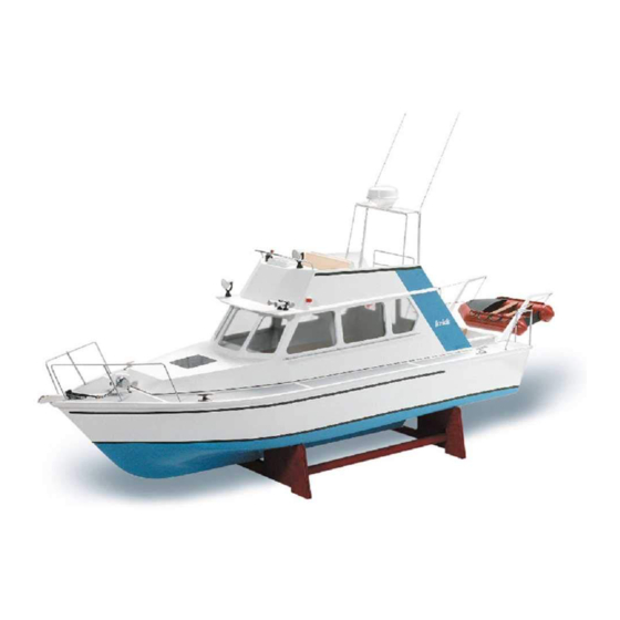
Building Instructions Lisa M.
Congratulations for buying this model kit of the
motor yacht „Lisa M.". This model is mainly
designed for the beginner, but is also a very
interesting kit for more experienced modellers
as a basis for own ideas.
For building this model you should have follow-
ing glues, fillers and paints:
- Superglue Krick ruck-zuck 20g thin (80491)
- Superglue Krick ruck-zuck 20g medium
(80495)
- 5min-Epoxy glue 100g (80479)
- wood glue UHU Holz waterresistant 75g
(48515)
- 2-component glue UHU-Plus acrylit 30g
(48315)
- Filler Micro-Fill white 295 ml (80480)
- Primer (Lord Nelson 80110)
- Clear Varnish for stairs, doors, (80112)
- paint spray blue (320053), light grey (Primer
and for deck), and white (320010)
- lacquer red, grey, silver and black for fittings
Following tools are recommended for building
"Lisa M.":
- modelling knife (416002)
- hand drill (473841)
Stand November 2007
Order-No. 20320
- sandpaper files (491016)
- sanding block (490080)
- sand paper of grane 180, 320, 400 and 600
(Set 490190)
- round file ca. Ø 6 mm
- drills Ø 1 mm, 1,5 mm, 2 mm, 3 mm, 4 mm,
6,5 mm
- wet sand paper 400 und 600 for filler, primer
and paints
When painting you should have masking tape
for areas, which should not be painted. A 3 mm
wide tape should be used for the water line.
For running and radio control you should have
following parts:
- 2 channel radio control including one Servo
- electronic speed control 20 A, forward/back
including BEC
- battery pack 7,2V NiCd, NiMH or lead battery
6V/1,1 Ah
- charger 220V AC or 12V DC
Many pictures in the following instruction
should make the building of the model as easy
as possible.
For identifying the laser cut parts in the
wooden sheets, there is a drawing at the end
Seite 1
©
Krick Modelltechnik Knittlingen
Advertisement

Related Manuals for Krick Lisa M.


Summary of Contents for Krick Lisa M.
- Page 1 6,5 mm ing glues, fillers and paints: - wet sand paper 400 und 600 for filler, primer and paints - Superglue Krick ruck-zuck 20g thin (80491) - Superglue Krick ruck-zuck 20g medium When painting you should have masking tape (80495) for areas, which should not be painted.
- Page 2 Then mark the rudder tube position 35 mm from the stern of the hull. Mark the position of the prop shaft 15 mm down from keel end. Seite 2 © Stand November 2007 Krick Modelltechnik Knittlingen...
- Page 3 Glue this support to the rudder tube, but do not yet glue all into the hull. Now make the battery and receiver tray with parts 19, 20 and 21. Seite 3 © Stand November 2007 Krick Modelltechnik Knittlingen...
- Page 4 Place the Servo temporarily into the tray and drill the holes with 1.5 mm drill fort he Servo screws. Servo Drill After that you can assemble the motor to the motor frame. Seite 4 © Stand November 2007 Krick Modelltechnik Knittlingen...
- Page 5 If some gaps have appeared, you can fill them out with filler. After the glue is set, you can also fix the rudder shaft in the same way. Seite 5 © Stand November 2007 Krick Modelltechnik Knittlingen...
- Page 6 (40) in place. When the glue is dry, bend the side Wenn der Kleber getrocknet ist, das Seitenteil according fo the curve of the roof and fix with superglue. Seite 6 © Stand November 2007 Krick Modelltechnik Knittlingen...
- Page 7 Then sand the side edges flush with the side walls. Now sand the flush the overlaying ends. 3. Front Windows In the next Stepp the front Windows 38 and 39 will be placed. Seite 7 © Stand November 2007 Krick Modelltechnik Knittlingen...
- Page 8 Now glue the cockpit to the superstructure. 42 45 First the parts 41 and 42 will be glued together. Place strips 3 x 5 x 40 mm for strengthening. Strip 3x5 mm Seite 8 © Stand November 2007 Krick Modelltechnik Knittlingen...
- Page 9 Then sand the curve. Now place the false edge (46) and glue to the roof. 7. Painting Now the superstructure can be sprayed with filler and sanded several times and afterwards Seite 9 © Stand November 2007 Krick Modelltechnik Knittlingen...
- Page 10 Make the seats from parts 53, 54, 55, 56 and brass wire 1,5 mm four supports (66). Fit the angle according to the angle of the side walls of the flybridge. Seite 10 © Stand November 2007 Krick Modelltechnik Knittlingen...
- Page 11 4. Ladder to Flybridge 30 mm Prepare parts 61, 64, 67 und 68 and build the ladder to the flybridge. Biegen Sie die Relingstütze aus Brass Wire 1,5 x 45 mm (69). Seite 11 © Stand November 2007 Krick Modelltechnik Knittlingen...
- Page 12 3 mm between wall and rail. Make the end piece at the left ladder rod from a piece of brass tube 2 x 7 mm (104) and glue. Seite 12 © Stand November 2007 Krick Modelltechnik Knittlingen...
- Page 13 Now the wooden parts should be fillered sanded and painted white or grey. Jetzt sollten die Holzteile mit Porenfüller la- ckiert und geschliffen werden. Afterwards place the motor (80) and capstan (81) with super glue. Seite 13 © Stand November 2007 Krick Modelltechnik Knittlingen...
- Page 14 Drill a hole of 1.5 mm into the base (102) and round the upper edges. Glue handle (104) on the lever. After painting the lever can be glued into the base. Seite 14 © Stand November 2007 Krick Modelltechnik Knittlingen...
- Page 15 Now cut ut the l5 laser parts from the sheet as wheel. Also place the 2 distance rings with shown. wood glue. Now you can stain and varnish the steering wheel and fix it at the helmstand. Seite 15 © Stand November 2007 Krick Modelltechnik Knittlingen...
- Page 16 At the end fit all other fittings to the model. For this several pictures are shown as follows. VI. Radio Control For running your model on the water, you will need a 2 channel radio control system with one servo. Seite 16 © Stand November 2007 Krick Modelltechnik Knittlingen...
- Page 17 Before assembly you should clear whether this is standing in ist neutral position, as a later screwing is difficult. Klaus Krick Modelltechnik, For steering the rudder first the rudder lever Postfach 1138, 75434 Knittlingen (97) needs to be fixed to the rudder shaft and Tel.
- Page 18 Laser Sheet 1,5 mm False Edge Roof Plywood Laser Sheet 1,5 mm False Edge Plywood 3 mm Rest False Edge Top Plywood 3 mm Rest Cockpit Floor Plywood Laser Sheet 3 mm Seite 18 © Stand November 2007 Krick Modelltechnik Knittlingen...
- Page 19 90 f Steering Wheel Axle Brass wire 1 x 10 mm Life Belt Finished Part Plastic Horn Finished Part Plastic Searchlight Finished Part Plastic Davit Finished Part Plastic Cleat Finished Part Metal Seite 19 © Stand November 2007 Krick Modelltechnik Knittlingen...
- Page 20 8 x 8 x 8 mm Lever Brass Wire 1,5 x 25 mm Handle Brass Tube 2 x 1,5 x 7 mm Connecting Clip Finished Part Door Handle Prass Wire 1,5 * 15 mm Seite 20 © Stand November 2007 Krick Modelltechnik Knittlingen...
- Page 21 Part Numbers of Laser Parts Seite 21 © Stand November 2007 Krick Modelltechnik Knittlingen...
Need help?
Do you have a question about the Lisa M. and is the answer not in the manual?
Questions and answers