Advertisement
Quick Links
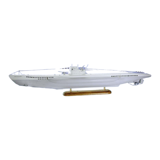
Technical data
Scale
Length
Width
Height (keel to top edge of tower)
Building Instructions
Congratulations on your purchase of this construction set. The submarine type VII was probably one of
the most built submarines in the world. In its time it set the standard and became very successful. We
hope that you will have a lot of fun building this model - either as a display version or a fully functional
diving model.
With this construction set you can either build a pure display model without any additional kit or a fully
functional diving model using the dive and drive set (Order no. 10311) which includes a flood tank and
pump. The diving rudders fore and aft were enlarged somewhat for the functional version in
comparison with the scale. Also, some covers on the hull of the diving model were designed to be
removable, which, on the standard version, do not, of course, have to be cut open. These instructions
apply to both models - any differences are clearly described.
You also need the following material to build the standard model:
- ABS special adhesive, order no. 80478
- Fast adhesive "Ruck-Zuck", order no. 80492
- UHU "plus endfest" 300 adhesive, order no. 45640
- UHU "plus Acrylit", order no. 48315
- UHU "allplast", order no. 48410
- Spray lacquer, colours light grey and dark grey
- Small pots of paint (Humbrol or similar), black
- Lead ballast strips, 60 g, order no. 60107 (2 off)
We recommend the following tools for the construction:
- Sharp and strong model building knife, order no. 416002
- Replacement blades for the knife, order no. 420019
- Drill bits, sizes 1 mm, 1.5 mm, 2 mm, 3 mm, 4 mm, 5 mm and possibly 7 mm
- Metal ruler
- Sanding block and sanding paper, various grades
- Round and flat files
SUBMARINE Type VII b
of the original
1:1
66.5 m
6.2 m
9.5 m
Page 1
of the model:
1:60
1120 mm
125 mm
170 mm
© Klaus Krick Modelltechnik Knittlingen August 2002
Advertisement

Subscribe to Our Youtube Channel
Related Manuals for Krick 20310


Summary of Contents for Krick 20310
- Page 1 - Drill bits, sizes 1 mm, 1.5 mm, 2 mm, 3 mm, 4 mm, 5 mm and possibly 7 mm - Metal ruler - Sanding block and sanding paper, various grades - Round and flat files Page 1 © Klaus Krick Modelltechnik Knittlingen August 2002...
- Page 2 20 years in our production and, with the outside of the model lacquered, had the best results with it. The best adhesive for this material is the Krick ABS special adhesive (order no. 80478). This adhesive dissolves the ABS very slightly and virtually welds the components together.
- Page 3 5 in the central removable part. Leave a gap of at least 37 mm in the area of the cut of the removable part (see drawing). Page 3 © Klaus Krick Modelltechnik Knittlingen August 2002...
- Page 4 Cut out the internal filler pieces for the bow (5) and the stern (6) as shown. Using a suitable rod that is fitted with some double-sided adhesive tape, the filler pieces, already glued, can then be inserted and pressed in as per the drawing. Page 4 © Klaus Krick Modelltechnik Knittlingen August 2002...
- Page 5 3 dots is aft starboard and 4 dots is fore starboard. Once the parts cleanly fit together, glue them in ensuring that the glue does not touch the central part. Page 5 © Klaus Krick Modelltechnik Knittlingen August 2002...
- Page 6 Re-fasten the central part to the hull and place it upside down. Draw the dimensions shown on the hull and glue the keel along the centre line to the hull. Let everything dry well. The edge of the facing area Page 6 © Klaus Krick Modelltechnik Knittlingen August 2002...
- Page 7 Cut out 3 strips for the cover which you then glue vertically to the inside of the cover. The cover should then be hooked in with its upper edge into the hull and slot into the lower edge by lifting it up and over. Page 7 © Klaus Krick Modelltechnik Knittlingen August 2002...
- Page 8 18mm from the central vertical line. Start drilling with a 2mm bit and increase the hole gradually whilst ensuring that the central point of the hole is maintained. [“Unterschale” =lower shell] Page 8 © Klaus Krick Modelltechnik Knittlingen August 2002...
- Page 9 M3 nut. Take care that the aperture is well sealed with adhesive. However, no adhesive should emerge from the top as it could inadvertently glue the nut fast, too. Page 9 © Klaus Krick Modelltechnik Knittlingen August 2002...
- Page 10 Now remove the pressure tank from the hull, apply ABS adhesive to the contact areas on the floor and replace it precisely in the same marked position. Re- Page 10 © Klaus Krick Modelltechnik Knittlingen August 2002...
- Page 11 Cut off the edge of the upper part and sand it level with the floor. Drill a 5mm hole each fore and aft into the front very close to the floor for the connection pipes (56) and glue these into place. Page 11 © Klaus Krick Modelltechnik Knittlingen August 2002...
- Page 12 The rudder shaft (48) is flattened at both ends 10mm from the end with a file to ease drilling. Now drill 1.5mm holes at the same angle at both ends. If these holes are not drilled at the same angle, the rudders will not be the same either. Page 12 © Klaus Krick Modelltechnik Knittlingen August 2002...
- Page 13 (51) with the already hooked-up wire (37), then stick the shaft through the second side of the vessel and mount the second fin there. Page 13 © Klaus Krick Modelltechnik Knittlingen August 2002...
- Page 14 This concludes the technical installation. The batteries really should be fixed to the floor with pieces of batten or velcro straps to prevent them moving about. Do this before your final trimming of the boat in your bath. Page 14 © Klaus Krick Modelltechnik Knittlingen August 2002...
- Page 15 (69) from outside starting from the outer side. Drill the compass (68) initially with 3mm, then cut it out from the outside. The rear of the compass is then cut out from the inside. Page 15 © Klaus Krick Modelltechnik Knittlingen August 2002...
- Page 16 4 as shown. Glue the upper part (65) to the lower part (64) with the deck (67). Then glue in the inner step (69). Page 16 © Klaus Krick Modelltechnik Knittlingen August 2002...
- Page 17 (78). Bend the balcony railing of the tower carefully around a round object of a suitable diameter and solder it to the supports. Now drill the 1mm holes for the supports into the floor of the Page 17 © Klaus Krick Modelltechnik Knittlingen August 2002...
- Page 18 The tank can be jammed between the cover fastening nuts using wedges and once you are sure about the final position in the deck, you can glue it into place there using double-sided adhesive tape. Page 18 © Klaus Krick Modelltechnik Knittlingen August 2002...
- Page 19 All these trials make submarine diving so enjoyable. We wish you a lot of fun with these tests and plenty of success. Krick Modelltechnik, P. O. Box 1138, D-75438 Knittlingen, Germany Web: www.krick-modell.de, E-Mail: service@krick-modell.de...
- Page 20 Item list for submarine type VIIb This item list contains both the parts of the construction box (order no. 20310) and of the diving set (order no. 20311) Part Description reqd. reqd. Qty. Material contained contained in basic in dive...
- Page 21 49 Screws for dive rudder Tin screw 2.2x45 mm 50 Rudder blade halves, dive ABS deep drawn part 1.5 rudder, dive model 51 Rudder lever, dive rudder, Finished article fore Page 21 © Klaus Krick Modelltechnik Knittlingen August 2002...
- Page 22 76 Periscope component Brass tube, 3x0.45x30 mm 77 Tower railing Brass wire, 1x470 mm in total 78 Tower, lower handrail Brass wire, 1x200 mm in total 79 Tower, handrail supports Splint Page 22 © Klaus Krick Modelltechnik Knittlingen August 2002...
- Page 23 Metal casting 90 Bollard Metal casting 91 Large bollard Metal casting 92 Rudder protection wire Brass wire 2x240 mm in total 93 Anchor Metal casting 94 “Shark” adhesive label adhesive label Page 23 © Klaus Krick Modelltechnik Knittlingen August 2002...
- Page 24 Min. 4 channel, not included A-E Receiver battery not included R-M Drive controller for motors 30A, not included R-P Controller/switch for pump not included Servo not included Pump, see part 57 Page 24 © Klaus Krick Modelltechnik Knittlingen August 2002...
- Page 25 Part numbers of cutting template: Page 25 © Klaus Krick Modelltechnik Knittlingen August 2002...
- Page 26 Builders Notes: Page 26 © Klaus Krick Modelltechnik Knittlingen August 2002...
Need help?
Do you have a question about the 20310 and is the answer not in the manual?
Questions and answers