Table of Contents
Advertisement
Advertisement
Table of Contents

Related Manuals for Exerpeutic 975XBT


Summary of Contents for Exerpeutic 975XBT
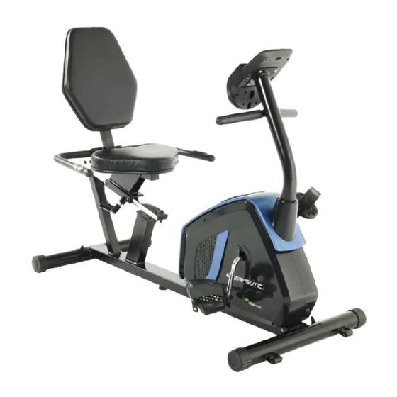
- Page 1 RECUMBENT BIKE GOLD 975XBT WITH 21 WORKOUT PROGRAMS IMPORTANT: Read all instructions carefully before using this product. Retain this owner’s manual for future reference. The specifications of this product may vary from this photo, subject to change without notice. OWNER’S MANUAL...
- Page 2 PLEASE DO NOT RETURN THIS PRODUCT TO THE STORE. STOP. Contact customer service if you have any questions regarding assembly or proper operation of the machine. Email us at: Service@paradigmhw.com Or call us at: 1-844-641-7921 Hours: 8:00 am to 5:00 pm (PST) Daily...
-
Page 3: Table Of Contents
TABLE OF CONTENT SERVICE ------------------------------------------------------------------------ LABEL PLACEMENT --------------------------------------------------------- IMPORTANT SAFETY GUIDELINES ------------------------------------- OVERVIEW DRAWING ---------------------------------------------------- PARTS LIST --------------------------------------------------------------------- HARDWARE & TOOLS PACK -------------------------------------------- REMOVE THE METAL TUBE--------------------------------------------- ASSEMBLY -------------------------------------------------------------------- CONSOLE --------------------------------------------------------------------- ADJUSTMENTS --------------------------------------------------------------- LUBRICATION----------------------------------------------------------------- TROUBLESHOOTING ------------------------------------------------------- TRANSPORT & STORAGE ------------------------------------------------ WARRANTY -------------------------------------------------------------------- PARTS REQUEST FORM---------------------------------------------------... -
Page 4: Service
SERVICE IMPORTANT: FOR NORTH AMERICA ONLY For damaged or defective product, questions, replacement parts or any other service support, please contact our customer service department by the below methods: For The Best Service, please Email: service@paradigmhw.com Response Time: 1-2 Business Days Emailing us with the information above will be the best method to receive a response during peak business hours Website:... -
Page 5: Label Placement
LABEL PLACEMENT... -
Page 6: Important Safety Guidelines
IMPORTANT SAFETY GUIDELINES Read all instructions before using the equipment. When using the equipment, basic precautions should always be followed. WARNING - To reduce the risk of injury to persons, read and understand the following: Make sure your equipment is correctly assembled before you use it. Be sure all screws, nuts, and bolts are tightened prior to use. - Page 7 IMPORTANT SAFETY GUIDELINES Do not use this equipment if you have any of the following conditions or ailments: Pregnancy Extreme obesity Middle ear infection Hiatus hernia or Ventral hernia Glaucoma, retinal detachment or conjunctivitis Use of anticoagulants including Aspirin in high doses. ...
-
Page 8: Overview Drawing
OVERVIEW DRAWING... -
Page 9: Parts List
PARTS LIST Description Description Main Frame Hand Pulse Wire B L=2100mm Spring Washer Φ6 Front Post Rear Stabilizer φ60*1.5*580 Flat Washer φ8*φ16*1.5 Wire Plug φ12.1 Seat Slide Tube Seat Post Knob M16*1.5*20 Handlebar Hex Socket Bolt M6*8 Front Stabilizer Self-Tapping Phillips Screw ST4.2*6 Stopper Φ18*8 Slide Tube Bracket... - Page 10 PARTS LIST Description Description Foam Grip II Φ30*Φ24*160 55 Right Cover 632*366*81 56 Motor Power Supply Cable 57 Flat Hex Nut 7/8” Lower Motor Wire 58 Flat Washer II Ф23*Ф34.5*δ2.5 Crank Cover Φ60*Φ26*6.5 59 Bearing Nut II 7/8” End Cap 60 Ball Bearing Hex Nut M8 61 Bearing Cup...
-
Page 11: Hardware & Tools Pack
HARDWARE & TOOLS LIST Silicon Oil 1 Bottle... -
Page 12: Remove The Metal Tube
REMOVE THE METAL TUBE TOOL 6mm Allen Wrench Remove the Metal Tubes from the Main Frame (1) by using 6mm Allen Wrench provided. Discard the metal tubes and hardware, they will not be used in assembly. -
Page 13: Assembly
ASSEMBLY TOOL Multi Hex Tool with Phillips Screwdriver STEP 1 1a. Insert the Cup Holder (53) into the Main Frame (1). See Figure A. 1b. Front Stabilizer Installation: Lift up the front of the Main Frame (1), and attach the Front Stabilizer (7) onto the front curve of the Main Frame (1) with two Carriage Bolts (9), two Curve Washers (10), two Spring Washers (12), and two Cap Nuts (11). - Page 14 ASSEMBLY The Cranks, Pedal Straps, Pedal Shafts, and Foot Pedals are marked “R” for Right and “L” for Left. TOOL Multi Hex Tool with Phillips Open Wrench Screwdriver Right Left STEP 2 2a. Installing the Left & Right Pedal Straps to the Pedals: Install the Left Pedal Strap (13) onto the Left Pedal (38).
- Page 15 ASSEMBLY Figure C TOOL 6mm Allen Wrench STEP 3 3a. Removal of Hardware for Installation: Remove four Hex Bolts (16), four Spring Washers (12) and four Curved Washers (10) from the Main Frame (1). Slide the Front Post Cover (37) onto the Front Post (2) before going onto the next sub step.
-
Page 16: Seat Post (
ASSEMBLY TOOL 6mm Allen Wrench STEP 4 4a. Removal of Hardware for Installation: Remove four Hex Bolts (84), four Spring Washers (85) and four Flat Washers (86) from the Seat Post (5). 4b. Installing the Seat Post to the Main Frame: Attach the Seat Post (5) inside the brackets of the Slide Tube Bracket (8) with four Hex Bolts (84), four Spring Washers (85) and four Flat Washers (86). - Page 17 ASSEMBLY TOOL Multi Hex Tool with Phillips Screwdriver STEP 5 5a. Removal of Hardware for Installation: Remove four Phillips Screws (26), four Spring Washers (29), and four Flat Washers (22) from the underside of the Seat (20). 5b. Installing the Seat to the Main Frame: Align the holes of the Seat (20) to the holes of the Seat Post (5).
- Page 18 ASSEMBLY TOOL Multi Hex Tool with Phillips Screwdriver PRE-INSTALLED HARDWARE (29) Spring (22) Flat (26) Phillips Washers Washer Screw 4PCS 4PCS 4PCS STEP 6 6a. Removal of Hardware for Installation: Remove four Phillips Screws (26), four Spring Washers (29) and the four Flat Washers (22) from the Backrest (21) with the Multi-Hex Tool with Phillips Screwdriver.
- Page 19 ASSEMBLY TOOL Multi Hex Tool with Phillips Screwdriver STEP 7 7a. Installing the Handlebar: Attach the Handlebar (6) onto the Seat Post (5) with two Hex Bolts (27), two Curved Washers (10), two Flat Washers (30), two Spring Washers (12) and two Cap Nuts (11).
-
Page 20: Hand Pulse Wire A (
ASSEMBLY TOOL Multi Hex Tool with Phillips Screwdriver Step 8 8a. Removal of Hardware for Installation: Remove four Phillips Screws (24) from the Console (23). 8b. Connecting the Console Wires: Connect the Lower Console Wire (17) from the Front Post (2) to the Upper Console Wire (87) from the Console (23). -
Page 21: Ac Adaptor (
ASSEMBLY STEP 9 – 9a. Plugging In The Machine Connect the AC Adaptor (19) to the cable plug on the front of the Left Cover (54). -
Page 22: Console
CONSOLE Display Information: TIME----------------------------------------------------- 00:00-99:00 SPEED ------------------------------------------------- 0.0-99.9 MPH / KM DISTANCE (DIST) ----------------------------------- 0.0-999.9 ML CALORIES (CAL) ------------------------------------ 0.0-999.9 CAL ODOMETER (ODO) --------------------------------- 0-999.9 ML CONSOLE BUTTONS: Start/Stop Button: Starts and pauses workouts. Mode Button: Switches displayed workout values: MPH/KMPH DIST WATT... - Page 23 CONSOLE Quick Start: Pressing START at the user selection screen will take you into a “QUICKSTART” manual workout using the selected user profile. You can set a consistent resistance level for the entire workout with ˄ ˅ buttons. Workout Program: Challenge yourself with one of the 21 preset workout programs.
- Page 24 CONSOLE CONSOLE FEATURES: ˄ ˅ CHANGE UNITS OF MEASUREMENT: Pressing and holding for 3 seconds will reset the console display and will change the units between Metric (kilometers) & Imperial (miles). Pressing and holding the START button for 3 seconds will reset the console display. Shut Off: The Console will go into standby after 4 minutes of inactivity.
-
Page 25: Adjustments
ADJUSTMENTS Rear Stabilizer (3) Adjustable Leveler (82) Rear Stabilizer End Cap (36) Adjusting the Rear Stabilizer End Cap and Adjustable Leveler Turn the Rear Stabilizer End Caps (36) on the Rear Stabilizer (3) as needed to level the recumbent bike. Turn the Adjustable Leveler (82) so that is making contact with the floor. -
Page 26: Lubrication
LUBRICATION Lubricating the Seat Slide Tube If the Backrest (21) is difficult to move along the Seat Slide Tube (4) when the Knob (32) has been loosened, apply ten drops of the Silicone Oil to the rear of the Seat Slide Tube (4). Grab the Backrest (21) to shift the Seat Slide Bracket (8) forward and backward to allow the Silicone Oil to evenly spread over the Seat Slide Tube (4). -
Page 27: Troubleshooting
TROUBLESHOOTING & MAINTENANCE TROUBLE SHOOTING 1. PROBLEM: The recumbent bike wobbles when in use. 1) SOLUTION: Turn the Rear Stabilizer End Caps (33) on the Rear Stabilizer (3) or Adjustable Leveler (82) on the bottom of the rear Main Frame (1) as needed to level the recumbent bike. - Page 28 TROUBLESHOOTING & MAINTENANCE Problem Potential Cause Correction 1. The motor does not Motor Problems activate Symptoms include an unusually loud noise coming from the Motor, which means the Gears are NOT meshing correctly. Try reversing the resistance and try again. If this fails then contact customer service.
-
Page 29: Transport & Storage
TRANSPORT & STORAGE Transporting the Bike Lift the Rear Stabilizer (3) with both hands until the Wheels (47) on the Front Stabilizer (7) make contact with the ground. Pull or Push the Bike to the desired storage area before gently lowering the Bike. -
Page 30: Warranty
WARRANTY MANUFACTURER’S LIMITED WARRANTY Paradigm Health & Wellness warrants to the original purchaser that this product is free from defects in material and workmanship when used for the purpose intended, under the conditions that it has been installed and operated in accordance with Paradigm’s Owner’s Manual. -
Page 31: Parts Request Form
PARTS REQUEST FORM Paradigm Health & Wellness, Inc. EMAIL THIS FORM WITH YOUR RECEIPT OF PURCHASE TO Service@paradigmhw.com NAME:_____________________________________________________________________________________ ADDRESS:__________________________________________________________________________________ CITY:________________________ STATE:_____________ ZIP:_______________________________________ TELEPHONE: (Day)______________________________________________________________________ (Night)_____________________________________________________________________ SERIAL#:___________________________________________________________________________________ MODEL#:___________________________________________________________________________________ PURCHASE DATE:___________________________________________________________________________ PLACE OF PURCHASE:_______________________________________________________________________ PART # DESCRIPTION “YOUR ORDER WILL BE PROCESSED WITHIN 3 BUSINESS DAYS” This form can also be faxed to #: 626-810-2166...
Need help?
Do you have a question about the 975XBT and is the answer not in the manual?
Questions and answers
What size battery for he 900xl