Table of Contents
Advertisement
Application Kit TC3X7 ADAS
Appl ication Kit Manual TC3X7 ADAS
Hardware: Application Kit TC3X7 ADAS V2.0
About this document
Scope and purpose
The User Manual provide information about using, configuration and connecting the Application Kit with
Infineon AURIX™ TC3X7 device.
This Application Kit Hardware Manual familiarizes you with the TriCore Evaluation Board and guides you through
the initial configuration of the Application Kit.
Intended audience
Design, verfication, test and software engineers will use this document to get an understanding of the
functionality and connections of the Application Kit.
User Manual
www.infineon.com
Please read the Important Notice and Warnings at the end of this document
Application Kit TC3X7 ADAS V2.0
V2.0
2018-06
Advertisement
Table of Contents

Related Manuals for Infineon TC3X7 ADAS


Summary of Contents for Infineon TC3X7 ADAS
- Page 1 Application Kit TC3X7 ADAS Appl ication Kit Manual TC3X7 ADAS Hardware: Application Kit TC3X7 ADAS V2.0 About this document Scope and purpose The User Manual provide information about using, configuration and connecting the Application Kit with Infineon AURIX™ TC3X7 device.
-
Page 2: Table Of Contents
Application Kit Manual TC3X7 ADAS Hardware: Application Kit TC3X7 ADAS V2.0 Table of Contents Table of Contents About this document ..............Preface-1 Table of Contents . -
Page 3: Table Of Contents
Application Kit Manual TC3X7 ADAS Hardware: Application Kit TC3X7 ADAS V2.0 Table of Contents Connector Pin Assignment ..............6-1 I/O connectors TC397 ADAS . -
Page 4: Introduction
Application Kit Manual TC3X7 ADAS Hardware: Application Kit TC3X7 ADAS V2.0 Introduction Introduction We congratulate you on your purchase of the TriCore Evaluation Board. This kit is a versatile tool, providing quick access to the capabilities of TriCore's powerful architecture. -
Page 5: Features
– Acoustic beeper – 100mm x 100mm Connectors The Application Kit TC3X7 ADAS offers a wide variety of connectors: – Standard power connector – Micro USB connector for ASC Interface (ASC0) and miniWiggler – RJ45 connector for Ethernet (if Ethernet supported by assembled CPU) –... -
Page 6: Block Diagram
Transceiver P10.6 I2C (P15) or QSPI4 (P22) P33.7 QSPI2 (P15) Multi Voltage System Acoustic Supply TLF3068xQVS01 4 LED’s Beeper (P13.0 up to P13.3) Figure 2-1 Application Kit TC3X7 ADAS Block Schematic User Manual V2.0 Application Kit TC3X7 ADAS V2.0 2018-06... -
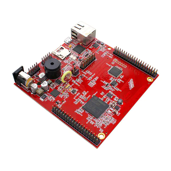
Page 7: Placement
Hardware: Application Kit TC3X7 ADAS V2.0 Features Placement BU301 D301 C114 D302 U203 U 301 C113 BT101 Y102 X301 X103 L103 U201 U202 X303 Figure 2-2 Application Kit TC3X7 ADAS V2.0 Top Placement User Manual V2.0 Application Kit TC3X7 ADAS V2.0 2018-06... - Page 8 Application Kit Manual TC3X7 ADAS Hardware: Application Kit TC3X7 ADAS V2.0 Features U305 U302 D102 D105 U303 U304 C109 LCD 201 L104 Figure 2-3 Application Kit TC3X7 ADAS V2.0 Bottom Placement User Manual V2.0 Application Kit TC3X7 ADAS V2.0 2018-06...
-
Page 9: Application Kit Information
The following boards are available: – Application Kit TC397 ADAS V2.0 Power Supply All needed voltages are generated via Infineon’s Multi Voltage System Supply TLF3068xQVS01. The board works with 3,3V IO. The TLF3068xQVS01 provide the following voltages: +3,3V for TriCore (connected to VEXT, VDDP3, VFLEX and used by RTC, Ethernet Phy, display and SD card) -
Page 10: Real Time Clock
Application Kit Manual TC3X7 ADAS Hardware: Application Kit TC3X7 ADAS V2.0 Application Kit Information – Configurable window watchdog – Configurable functional watchdog (not with TLF30682QVS01) – Microcontroller monitoring via ERR pin (not with TLF30682QVS01) – Green Product (RoHS compliant) – ISO26262 compliant up to ASIL D (not with TLF30682QVS01) –... -
Page 11: Read A Display Register
Application Kit Manual TC3X7 ADAS Hardware: Application Kit TC3X7 ADAS V2.0 Application Kit Information first 10 bit transfer Bit 9 must be 0, this will be indicate a write access. Bit 8 must be 1, this will be indicate an endless transfer. -
Page 12: Micro Sd Card
Application Kit Manual TC3X7 ADAS Hardware: Application Kit TC3X7 ADAS V2.0 Application Kit Information Micro SD card The board has a slot to use the board with an micro SD card. If the assembled CPU contains a SDMMC module then this is connected directly to the SD card. -
Page 13: Beeper
Application Kit Manual TC3X7 ADAS Hardware: Application Kit TC3X7 ADAS V2.0 Application Kit Information Beeper The board has an electro-acoustic transducer which can be used for an acoustic output. The transducer is connected to pin P33.0 and needs a 2048Hz frequency. -
Page 14: Debug System
Application Kit Manual TC3X7 ADAS Hardware: Application Kit TC3X7 ADAS V2.0 Application Kit Information The WAKE button (S102) will be used to enable/wakeup the TLF3068x. 3.17 Debug System 3.17.1 OCDS1 The OCDS1 signals are connected to the IDC16 plug (X401). They work with the port supply of Microcontroller (+5V default or +3,3V). -
Page 15: Application Kit Configuration
Application Kit Manual TC3X7 ADAS Hardware: Application Kit TC3X7 ADAS V2.0 Application Kit Configuration Application Kit Configuration The Application Kit has a fixed configuration which can be sligthly changed. For locating components see Figure 7-5 Figure 7-6. Default Pad State The default pad state is that the internal pull-up devices on the I/O pins are enabled. -
Page 16: Signal (On Board Used) Description
Application Kit Manual TC3X7 ADAS Hardware: Application Kit TC3X7 ADAS V2.0 Signal (on board used) Description Signal (on board used) Description For more information about the signals please see the user manual/datasheet for TC3X7 and/or the schematics of the board. -
Page 17: Clock Signals
Application Kit Manual TC3X7 ADAS Hardware: Application Kit TC3X7 ADAS V2.0 Signal (on board used) Description Clock Signals Table 5-4 Clock Signals Short name Description XTAL1 Crystal Oscillator Input XTAL2 Crystal Oscillator Output Debug Signals Table 5-5 Debug Signals Short name... - Page 18 Application Kit Manual TC3X7 ADAS Hardware: Application Kit TC3X7 ADAS V2.0 Signal (on board used) Description Table 5-6 Peripheral Signals (continued) Short name Description P11.9 Ethernet RXD1 Input A P11.10 Ethernet RXD0 Input A P11.11 Ethernet RCTL Input A P11.12 Ethernet RXCLK Input A P12.0...
- Page 19 Application Kit Manual TC3X7 ADAS Hardware: Application Kit TC3X7 ADAS V2.0 Signal (on board used) Description Table 5-6 Peripheral Signals (continued) Short name Description P20.10 SDMMC0 Data 2 Input/Output for SD card P20.11 SDMMC0 Data 3 Input/Output for SD card P50.0 / D1_N...
-
Page 20: Connector Pin Assignment
Application Kit Manual TC3X7 ADAS Hardware: Application Kit TC3X7 ADAS V2.0 Connector Pin Assignment Connector Pin Assignment The Application Kit will be shipped with two 40 pin male (plug) connectors on top layer with a standard grid of 2,54mm. I/O connectors TC397 ADAS... -
Page 21: Usb Connector Pinout
Application Kit Manual TC3X7 ADAS Hardware: Application Kit TC3X7 ADAS V2.0 Connector Pin Assignment USB connector pinout Figure 6-3 USB connector pinout (Micro USB B-type) CAN connector pinout Figure 6-4 CAN connector pinout (IDC10) LIN connector pinout Figure 6-5 LIN connector pinout (IDC10) User Manual V2.0... -
Page 22: Ethernet Connector Pinout
Application Kit Manual TC3X7 ADAS Hardware: Application Kit TC3X7 ADAS V2.0 Connector Pin Assignment Ethernet connector pinout Figure 6-6 Ethernet connector pinout (RJ45) MMIC / RIF connector pinout 10 12 14 16 18 20 22 11 13 15 17 19 21... -
Page 23: Dap Connector Pinout
Application Kit Manual TC3X7 ADAS Hardware: Application Kit TC3X7 ADAS V2.0 Connector Pin Assignment DAP connector pinout Figure 6-9 DAP connector pinout (Samtec FTSH10) User Manual V2.0 Application Kit TC3X7 ADAS V2.0 2018-06... -
Page 24: Schematic And Layout
Application Kit Manual TC3X7 ADAS Hardware: Application Kit TC3X7 ADAS V2.0 Schematic and Layout Schematic and Layout Known problems No problems known. Schematic User Manual V2.0 Application Kit TC3X7 ADAS V2.0 2018-06... - Page 25 Application Kit Manual TC3X7 ADAS Hardware: Application Kit TC3X7 ADAS V2.0 Schematic and Layout Figure 7-1 Schematic - Project Overview User Manual V2.0 Application Kit TC3X7 ADAS V2.0 2018-06...
- Page 26 Application Kit Manual TC3X7 ADAS Hardware: Application Kit TC3X7 ADAS V2.0 Schematic and Layout Figure 7-2 Schematic - CPU and Power Supply User Manual V2.0 Application Kit TC3X7 ADAS V2.0 2018-06...
- Page 27 Application Kit Manual TC3X7 ADAS Hardware: Application Kit TC3X7 ADAS V2.0 Schematic and Layout Figure 7-3 Schematic - On Board Peripherals User Manual V2.0 Application Kit TC3X7 ADAS V2.0 2018-06...
- Page 28 Application Kit Manual TC3X7 ADAS Hardware: Application Kit TC3X7 ADAS V2.0 Schematic and Layout Figure 7-4 Schematic - miniWiggler JDS , Debug connectors and RIF/MMIC connector User Manual V2.0 Application Kit TC3X7 ADAS V2.0 2018-06...
-
Page 29: Layout
Application Kit Manual TC3X7 ADAS Hardware: Application Kit TC3X7 ADAS V2.0 Schematic and Layout Layout BU301 R239 R247 R245 D201 R241 R246 CB305 CB302 R 308 D301 C114 R222 C205 U 203 U301 CB214 Q301 R 318 D302 R328 U 307... - Page 30 Application Kit Manual TC3X7 ADAS Hardware: Application Kit TC3X7 ADAS V2.0 Schematic and Layout R224 U305 C211 R250 C210 R240 CB306 R324 C301 C215 U302 R242 R321 R305 R119 CB211 R306 D102 D105 CB210 C212 CB304 R131 R326 U303 R137...
-
Page 31: Layout With Dimensioning
Application Kit Manual TC3X7 ADAS Hardware: Application Kit TC3X7 ADAS V2.0 Schematic and Layout Layout with Dimensioning The following dimensions should be used for development of extension boards. BU301 R239 R247 R245 D201 R241 R246 CB305 CB302 R308 D301 C114... - Page 32 Application Kit Manual TC3X7 ADAS Hardware: Application Kit TC3X7 ADAS V2.0 Schematic and Layout BU301 R239 R247 R245 D201 R241 R246 CB305 CB302 R308 D301 C114 R222 C205 U203 U301 CB214 Q 301 R318 D302 R328 U307 CB317 CB316 C113...
- Page 33 Application Kit Manual TC3X7 ADAS Hardware: Application Kit TC3X7 ADAS V2.0 Revision History Page or Item Subjects (major changes since previous revision) V2.0, 2018-06 Adapt to new board version V2.0 with Gigabit Ethernet User Manual RevisionHistory-1 V2.0 Application Kit TC3X7 ADAS V2.0...
- Page 34 Infineon Technologies, Infineon Technologies in customer's applications. Document reference Infineon Technologies’ products may not be used in The data contained in this document is exclusively Doc_Number any applications where a failure of the product or any intended for technically trained staff.
Need help?
Do you have a question about the TC3X7 ADAS and is the answer not in the manual?
Questions and answers