Infineon PSOC Control C3M5 User Manual
Digital power control card
Hide thumbs
Also See for PSOC Control C3M5:
- Quick start manual (4 pages) ,
- Quick start manual (2 pages) ,
- Quick start manual (2 pages)
Table of Contents
Advertisement
Quick Links
KIT_PSC3M5_CC1 PSOC
Control C3M5 Digital Power
™
Control Card user guide
About this document
Scope and purpose
This document describes the features and hardware details of the PSOC
Control C3M5 Digital Power Control
™
®
Card. It is designed to provide an evaluation platform for digital control applications with the PSOC
Arm
™
®
Cortex
-M33 based MCU. This board is part of Infineon's digital power evaluation platform kits.
Intended audience
This document is intended for KIT_PSC3M5_CC1 users, and this board is intended to be used under laboratory
conditions.
User guide
Please read the sections "Important notice" and "Warnings" at the end of this document
002-39715 Rev. *B
www.infineon.com
2024-12-16
Advertisement
Table of Contents

Related Manuals for Infineon PSOC Control C3M5


Summary of Contents for Infineon PSOC Control C3M5
-
Page 1: About This Document
Card. It is designed to provide an evaluation platform for digital control applications with the PSOC ™ ® Cortex -M33 based MCU. This board is part of Infineon’s digital power evaluation platform kits. Intended audience This document is intended for KIT_PSC3M5_CC1 users, and this board is intended to be used under laboratory conditions. -
Page 2: Important Notice
Boards provided by Infineon Technologies. The design of the Evaluation Boards and Reference Boards has been tested by Infineon Technologies only as described in this document. The design is not qualified in terms of safety requirements, manufacturing and operation over the entire operating temperature range or lifetime. -
Page 3: Safety Precautions
KIT_PSC3M5_CC1 PSOC Control C3M5 Digital Power Control Card ™ user guide Safety precautions Safety precautions Note: Please note the following warnings regarding the hazards associated with development systems. Table 1 Safety precautions Caution: The evaluation or reference board contains parts and assemblies sensitive to electrostatic discharge (ESD). -
Page 4: Table Of Contents
KIT_PSC3M5_CC1 PSOC Control C3M5 Digital Power Control Card ™ user guide Table of contents Table of contents About this document ..............1 Important notice . -
Page 5: Introduction
Control C3M5 MCU and create your own design. These ™ examples can be accessed through the ModusToolbox Project Creator tool. Alternatively, you can also visit ™ Infineon’s code examples for the ModusToolbox software page to access these examples ™ Key features... - Page 6 KIT_PSC3M5_CC1 PSOC Control C3M5 Digital Power Control Card ™ user guide 1 Introduction • Power supply of PSOC Control C3M5 ™ Via evaluation board (5 V) converted to 3.3 V Via debug USB connector, 5 V DC-DC isolater, and converted to 3.3 V •...
-
Page 7: Kit Operation
KIT_PSC3M5_CC1 PSOC Control C3M5 Digital Power Control Card ™ user guide 2 Kit operation Kit operation The PSOC Control C3M5 Digital Power Control Card is an evaluation board designed to help engineers in ™ learning and testing the digital power control applications. The board features a PSOC Control C3M5 MCU ™... -
Page 8: Using The Out Of The Box Example
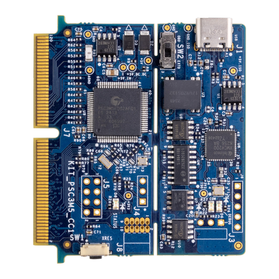
KIT_PSC3M5_CC1 PSOC Control C3M5 Digital Power Control Card ™ user guide 2 Kit operation GND_ISO SCL_ISO SDA_ISO SWIO_TMS +3V3 SWCLK_TCK XRES_L Figure 2 PSOC Control C3M5 Digital Power Control Card hardware description (2) ™ Using the Out of the box example The PSOC Control C3M5 Digital Power Control Card coming with the interface board is by default programmed ™... -
Page 9: Creating A Project And Program/Debug Using Modustoolbox ™ Software
KIT_PSC3M5_CC1 PSOC Control C3M5 Digital Power Control Card ™ user guide 2 Kit operation Ensure that the PSOC Control C3M5 Digital Power Control Card is mounted on the interface board using ™ the 120-pin Edge connector Connect the kit to your PC using the provided USB cable through the J-Link USB connector Open a terminal program and select the COM port. - Page 10 KIT_PSC3M5_CC1 PSOC Control C3M5 Digital Power Control Card ™ user guide 2 Kit operation Note: The programming can be done either with the onboard JLink debugger or by attaching an external debugger to the connector J8 on the board. The user can easily switch between the onboard debugger or external debugger by setting the switch SW2 to the desired position.
- Page 11 KIT_PSC3M5_CC1 PSOC Control C3M5 Digital Power Control Card ™ user guide 2 Kit operation Figure 5 Create new application Select the BSP -KIT_PSC3M5_CC1 in the Choose Board Support Package window and click Next Figure 6 Creating a new application: Choose Board Support Package User guide 002-39715 Rev.
- Page 12 KIT_PSC3M5_CC1 PSOC Control C3M5 Digital Power Control Card ™ user guide 2 Kit operation Select the application in the Select Application window and click Create Figure 7 Creating a new application: Select Application To build and program a PSOC Control C3M5 MCU application: ™...
- Page 13 KIT_PSC3M5_CC1 PSOC Control C3M5 Digital Power Control Card ™ user guide 2 Kit operation To debug a PSOC Control C3M5 MCU application: ™ In the Project Explorer, select <App_Name> project In the Quick Panel, click the <App_Name> Debug (JLink) configuration from the Launches section, as shown in Figure 9 Figure 9...
-
Page 14: Hardware
KIT_PSC3M5_CC1 PSOC Control C3M5 Digital Power Control Card ™ user guide 3 Hardware Hardware Hardware functional description This section explains the individual hardware blocks. 3.1.1 PSOC Control C3M5 Digital Power Control Card ™ 5V_ISO 5V_DC_DC 5V_IN TYPE-C DC-DC Isolator 10 pin 8 pin 5 V to 3.3 V 5 V to 3.3 V... -
Page 15: Psoc ™ Control C3M5 Mcu
KIT_PSC3M5_CC1 PSOC Control C3M5 Digital Power Control Card ™ user guide 3 Hardware 3.1.2 PSOC Control C3M5 MCU ™ Figure 11 Block diagram PSOC Control C3M5 MCU ™ PSC3M5xD devices are based on the Arm ® Cortex ® -M33, running up to 180 MHz with DSP and FPU capability. In addition to the CPU subsystem, the devices contain advanced real-time control peripherals, such as a high- performance programmable analog subsystem, comparators, advanced timers with high-resolution capability, up to six SCBs, and two CAN FDs for communication. - Page 16 KIT_PSC3M5_CC1 PSOC Control C3M5 Digital Power Control Card ™ user guide 3 Hardware 5 V from 120-pin connector Isolated 5 V to 3.3 V 3.3 V to PSOC™ C3M5 MCU 5 V from Type-C USB connector 5 V to 5 V Isolated DC-DC Converter 120-pin...
-
Page 17: Psoc ™ Control C3M5 Mcu I/Os
Approved By Approved By Approved By Infineon Technologies hereby disclaims any and all warranties and Infineon Technologies hereby disclaims any and all warranties and Infineon Technologies hereby disclaims any and all warranties and liabilities of any kind, including without limitation, warranties of... -
Page 18: 120-Pin Edge Finger Interface
KIT_PSC3M5_CC1 PSOC Control C3M5 Digital Power Control Card ™ user guide 3 Hardware 3.1.5 120-pin Edge finger interface Figure 16 120-pin Edge finger User guide 002-39715 Rev. *B 2024-12-16... -
Page 19: Analog-To-Digital Converter (Adc) Input Filter
KIT_PSC3M5_CC1 PSOC Control C3M5 Digital Power Control Card ™ user guide 3 Hardware The control card has a 120-pin Edge finger, which is inserted into a mating connector (HSEC8-160-01-L-DV-A-BL) on evaluation boards. All the IO lines of the PSOC C3M5 device are routed to this 120-pin Edge finger. The ™... -
Page 20: Reset Button
DDIO_0_0 DDIO_0_1 VAREF_EXT DDIO_0_2 VAREF_EXT VAREF_EXT_C KIT_PSC3M5_CC1 PSOC Control C3M5 Digital Power Control Card ™ 0.1uF DDIO_1 VSS_1 user guide VSS_2 VSS_3 SS_5 VSS_4 3 Hardware SC3M5FDS2AFQ1 3.1.7 Reset button +3V3 0 OHM ECO_OUT [7] 5.1K 6MHZ ECO_IN [7] [4,8,9] XRES_L TL3330AF260QG 0.1uF... -
Page 21: Digital Isolators
KIT_PSC3M5_CC1 PSOC Control C3M5 Digital Power Control Card ™ user guide 3 Hardware 3.1.9 Digital isolators Figure 20 Digital isolators The control card has an onboard XMC4200-based JLink debugger. All the signals connected between the XMC4200 and PSOC C3M5 devices are isolated with digital isolators. These digital isolators can provide ™... -
Page 22: Psoc ™ C3M5 Interface Board
KIT_PSC3M5_CC1 PSOC Control C3M5 Digital Power Control Card ™ user guide 3 Hardware 3.1.10 PSOC C3M5 Interface Board ™ Figure 21 PSOC C3M5 Interface Board schematics ™ User guide 002-39715 Rev. *B 2024-12-16... - Page 23 KIT_PSC3M5_CC1 PSOC Control C3M5 Digital Power Control Card ™ user guide 3 Hardware Figure 22 PSOC C3M5 Interface board ™ Figure 23 PSOC C3M5 Interface Board and Control Card ™ The interface board is made as an interface for the PSOC C3M5 Control Card.
-
Page 24: Psoc ™ Control C3M5 Mcu Clock Architecture
™ Size Size Size Infineon Technologies hereby disclaims any and all warranties and Infineon Technologies hereby disclaims any and all warranties and Infineon Technologies hereby disclaims any and all warranties and liabilities of any kind, including without limitation, warranties of... -
Page 25: Xmc4200 As Onboard Programmer/Debugger
KIT_PSC3M5_CC1 PSOC Control C3M5 Digital Power Control Card ™ user guide 3 Hardware 3.1.13 XMC4200 as onboard programmer/debugger Figure 26 XMC4200 MCU based on board JLink programmer/debugger The PSOC Control C3M5 Digital Power Control Card supports on board isolated debug interface: ™... -
Page 26: Removing The Onboard Debugger
KIT_PSC3M5_CC1 PSOC Control C3M5 Digital Power Control Card ™ user guide 3 Hardware 3.1.14 Removing the onboard debugger XMC4200 JLINK debugger 10 pin SWD/JTAG debug option 8 pin SWD/UART debug option Figure 27 Debug options when removing debugger part of control card PSOC Control C3M5 Digital Power Control Card can be broken off into two parts by breaking the PCB, as shown ™... -
Page 27: Production Data
KIT_PSC3M5_CC1 PSOC Control C3M5 Digital Power Control Card ™ user guide 4 Production data Production data The board has been designed with Allegro. The full PCB design data (schematics, layout, and BOM) of this board can also be downloaded from the webpage. -
Page 28: Revision History
KIT_PSC3M5_CC1 PSOC Control C3M5 Digital Power Control Card ™ user guide Revision history Revision history Document revision Date Description of changes 2024-07-16 Initial release 2024-08-01 Replaced the word "Expansion" with "Evaluation" in the document 2024-12-16 Updated: Safety precautions Kit contents Getting started Key features Kit operation... -
Page 29: Disclaimer
Infineon Technologies, Email: erratum@infineon.com Infineon Technologies’ products may not be used in any applications where a failure of the product or any consequences of the use thereof can reasonably be Document reference expected to result in personal injury.
Need help?
Do you have a question about the PSOC Control C3M5 and is the answer not in the manual?
Questions and answers