Siemens SINAMICS S120 System Manual
Hydraulic drive
Hide thumbs
Also See for SINAMICS S120:
- Function manual (1094 pages) ,
- Diagnostic manual (947 pages) ,
- Manual (848 pages)
Table of Contents
Advertisement
Quick Links
Advertisement
Table of Contents

Related Manuals for Siemens SINAMICS S120


Summary of Contents for Siemens SINAMICS S120
- Page 3 ___________________ Hydraulic Drive Preface Fundamental safety ___________________ instructions ___________________ SINAMICS System overview ___________________ Configuration S120 Hydraulic Drive ___________________ Commissioning ___________________ Drive functions System Manual ___________________ Hardware ___________________ Appendix Valid from: Firmware version 4.7 04/2015 6SL3097-4BA00-0BP1...
- Page 4 Note the following: WARNING Siemens products may only be used for the applications described in the catalog and in the relevant technical documentation. If products and components from other manufacturers are used, these must be recommended or approved by Siemens. Proper transport, storage, installation, assembly, commissioning, operation and maintenance are required to ensure that the products operate safely and without any problems.
-
Page 5: Preface
(mailto:docu.motioncontrol@siemens.com). My Documentation Manager At the following address (http://www.siemens.com/mdm), you can find information on how to create your own individual documentation based on Siemens' content, and adapt it for your own machine documentation. Training At the following address (http://www.siemens.com/sitrain), you can find information about SITRAIN (Siemens training on products, systems and solutions for automation and drives). - Page 6 Equipment for Machine Tools (Catalog NC 61) SINUMERIK 840D sl Type 1B • Equipment for Machine Tools (Catalog NC 62) Installation/assembly SINAMICS S120 Equipment Manual for Control Units and • Additional System Components SINAMICS S120 Equipment Manual for Booksize Power •...
- Page 7 Technical Support Country-specific telephone numbers for technical support are provided in the Internet at the following address (https://support.industry.siemens.com/sc/ww/en/sc/2090) in the "Contact" area. Hydraulic Drive System Manual, 04/2015, 6SL3097-4BA00-0BP1...
- Page 8 (https://support.industry.siemens.com/cs/ww/en/ps/13231/cert). You can obtain an up-to-date list of currently certified components on request from your local Siemens office. If you have any questions relating to certifications that have not yet been completed, please ask your Siemens contact person.
- Page 9 EMC limit values are ensured. Spare parts Spare parts are available on the Internet at the following address (https://support.industry.siemens.com/sc/ww/en/sc/2110). Ground symbols Table 2 Symbols...
- Page 10 Preface Notation The following notation and abbreviations are used in this documentation: Notation for faults and alarms (examples): Fault 12345 • F12345 Alarm 67890 • A67890 Safety message • C23456 Notation for parameters (examples): Adjustable parameter 918 • p0918 Display parameter 1024 •...
-
Page 11: Table Of Contents
2.1.7 SINUMERIK / SINAMICS......................28 2.1.8 Hydraulic power unit ....................... 28 SINAMICS S120 HLA module components................29 Comparison of electric and hydraulic drive systems .............. 30 System data ..........................32 2.4.1 Climatic and mechanical environmental conditions in operation ..........32 2.4.2... - Page 12 Table of contents Commissioning ............................. 53 Commissioning overview ....................... 53 Configuration - hydraulic module ................... 54 Configuration - valve selection ....................55 Configuration - valve data ...................... 56 Configuration - save valve data ..................... 57 Configuration - cylinder data ....................58 Configuration - supply data ....................
- Page 13 Table of contents 4.18.8 Hydraulic/electrical interpolation ................... 123 4.19 Commissioning functions ...................... 123 4.19.1 Measuring function ........................ 124 4.19.2 Function generator ........................ 132 4.19.2.1 Valve spool setpoint (control voltage) ................... 133 4.19.2.2 Velocity setpoint ........................134 4.19.2.3 Position setpoint ........................135 4.19.3 Circularity test ........................
- Page 14 Table of contents Interfaces ..........................202 6.2.1 X200-X203 DRIVE-CLiQ interfaces ..................203 6.2.2 X224 electronics power supply .................... 204 6.2.3 X231 and X232 encoder system interface ................205 6.2.4 X241 and X242 pressure sensors on the cylinder side (A/B) ..........208 6.2.5 X251 and X252 pressure sensors to sense the pressure at the shutoff valve ....
-
Page 15: Fundamental Safety Instructions
Fundamental safety instructions Fundamental safety instructions for Hydraulic Drive WARNING Risk of death if the safety instructions and remaining risks are not carefully observed If the safety instructions and residual risks are not observed in the documentation associated with the hydraulic components, accidents involving severe injuries or death can occur. -
Page 16: Fundamental Safety Instructions
Fundamental safety instructions 1.2 Fundamental safety instructions Fundamental safety instructions 1.2.1 General safety instructions DANGER Danger to life due to live parts and other energy sources Death or serious injury can result when live parts are touched. • Only work on electrical devices when you are qualified for this job. •... - Page 17 Fundamental safety instructions 1.2 Fundamental safety instructions WARNING Danger to life when live parts are touched on damaged devices Improper handling of devices can cause damage. For damaged devices, hazardous voltages can be present at the enclosure or at exposed components;...
- Page 18 Fundamental safety instructions 1.2 Fundamental safety instructions WARNING Danger to life through unexpected movement of machines when using mobile wireless devices or mobile phones Using mobile wireless devices or mobile phones with a transmit power > 1 W closer than approx.
- Page 19 Fundamental safety instructions 1.2 Fundamental safety instructions NOTICE Device damage caused by incorrect voltage/insulation tests Incorrect voltage/insulation tests can damage the device. • Before carrying out a voltage/insulation check of the system/machine, disconnect the devices as all converters and motors have been subject to a high voltage test by the manufacturer, and therefore it is not necessary to perform an additional test within the system/machine.
-
Page 20: Safety Instructions For Electromagnetic Fields (Emf)
Fundamental safety instructions 1.2 Fundamental safety instructions 1.2.2 Safety instructions for electromagnetic fields (EMF) WARNING Danger to life from electromagnetic fields Electromagnetic fields (EMF) are generated by the operation of electrical power equipment such as transformers, converters or motors. People with pacemakers or implants are at a special risk in the immediate vicinity of these devices/systems. -
Page 21: Industrial Security
Siemens recommends strongly that you regularly check for product updates. For the secure operation of Siemens products and solutions, it is necessary to take suitable preventive action (e.g. cell protection concept) and integrate each component into a holistic, state-of-the-art industrial security concept. -
Page 22: Residual Risks Of Power Drive Systems
Fundamental safety instructions 1.2 Fundamental safety instructions 1.2.5 Residual risks of power drive systems The control and drive components of a drive system are approved for industrial and commercial use in industrial line supplies. Their use in public line supplies requires a different configuration and/or additional measures. - Page 23 Fundamental safety instructions 1.2 Fundamental safety instructions 3. Hazardous shock voltages caused by, for example, – Component failure – Influence during electrostatic charging – Induction of voltages in moving motors – Operation and/or environmental conditions outside the specification – Condensation/conductive contamination –...
- Page 24 Fundamental safety instructions 1.2 Fundamental safety instructions Hydraulic Drive System Manual, 04/2015, 6SL3097-4BA00-0BP1...
-
Page 25: System Overview
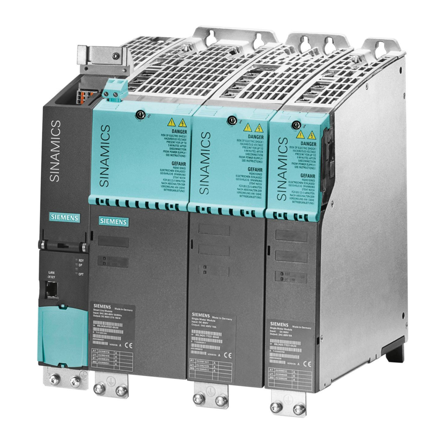
System overview Structure of a hydraulic drive Figure 2-1 Example of a SINAMICS drive system with electrical and hydraulic components Hydraulic Drive System Manual, 04/2015, 6SL3097-4BA00-0BP1... -
Page 26: Machine Guidance
System overview 2.1 Structure of a hydraulic drive 2.1.1 Machine guidance Guidance systems Guidance for straight-line movement of machine slides and tables is accomplished with minimum friction and maximum precision using hydrodynamic and hydrostatic slideways or roller slideways. Friction A certain degree of friction can be very useful for damping oscillations. However, excessive friction, especially pronounced transitions from static to sliding friction, has a negative effect on the control result and impairs control loop stability. -
Page 27: Servo Solenoid Valve
System overview 2.1 Structure of a hydraulic drive 2.1.3 Servo solenoid valve Task The servo solenoid valve is the final controlling element in the control loop and forms the electro-hydraulic converter. Function The valve continuously converts electrical signals into hydraulic flow. Its quality is defined by static and dynamic parameters, such as: ●... -
Page 28: Position Measuring System
System overview 2.1 Structure of a hydraulic drive 2.1.6 Position measuring system The position measuring system supplies the actual value for the position of the moving machine element. Function The velocity is acquired by continuously differentiating the distance with respect to time. Various systems are available depending on the level of accuracy required. -
Page 29: Sinamics S120 Hla Module Components
● CU320-2 Control Unit, NCU-integrated or NX for processing drive and technology functions ● 24 V power supply This power supply is used to internally supply the SINAMICS S120 HLA and is also required by the various sensors. ● 26.5 V power supply... -
Page 30: Comparison Of Electric And Hydraulic Drive Systems
System overview 2.3 Comparison of electric and hydraulic drive systems Comparison of electric and hydraulic drive systems Table 2- 1 Comparison of electric and hydraulic drive systems Criterion Direct electric drive Electric drive with leadscrew Hydraulic drive Power density / Low weight Servomotor and leadscrew Cylinder and servo solenoid... - Page 31 System overview 2.3 Comparison of electric and hydraulic drive systems Criterion Direct electric drive Electric drive with leadscrew Hydraulic drive Noise Linear guide noise in opera- Servomotor and leadscrew Possible noise caused by flow • tion noise in operation through the valve Pump noise of the hydraulic •...
-
Page 32: System Data
System overview 2.4 System data System data 2.4.1 Climatic and mechanical environmental conditions in operation Note The following information refers to the electrical section of the HLA module, however, not to external hydraulic components. Climatic environmental conditions If the specified values cannot be maintained, then a heat exchanger or air conditioner must be provided. -
Page 33: Transport And Storage Conditions
System overview 2.4 System data 2.4.2 Transport and storage conditions Originally packaged modules The following data applies to modules in their original packaging. Table 2- 4 Climatic conditions Function Remark Value Temperature range Lower temperature limit -25 °C Upper temperature limit +55 °C Relative air No rain, no condensation, no spray water, no for-... - Page 34 System overview 2.4 System data Hydraulic Drive System Manual, 04/2015, 6SL3097-4BA00-0BP1...
-
Page 35: Configuration
The functions of SINAMICS components are described with keywords in this manual. Limit values for functions may be specified in some cases. Please refer to the SINAMICS S120 and SINUMERIK 840Dsl commissioning instructions for additional details (e.g. characteristics). Phase 1 1. -
Page 36: Procedure For Configuring The Hydraulics
Configuration 3.2 Integration in SINUMERIK/SINAMICS S120 3.1.2 Procedure for configuring the hydraulics The hydraulic configuring phase is divided into the following steps: 1. Selecting the cylinder Based on the required forces and velocities required and the cylinder mounting conditions in the machine 2. -
Page 37: Configuring The Hydraulics
Configuration 3.3 Configuring the hydraulics Configuring the hydraulics 3.3.1 Cylinder selection Piston and rod diameters The piston and rod diameters are calculated according to Pascal's theorem on the basis of the necessary compressive and tensile forces F and a standard pressure value of p = 40 bis 100 bar for machine tools (a maximum pressure of 350 bar is permitted). - Page 38 Configuration 3.3 Configuring the hydraulics Mounting In order to ensure good control quality, backlash-free mountings, e.g. base or flange mountings, must be used. Flange mounting ① Flange at front ② Flange at rear ③ Foot mounting Figure 3-1 Cylinder mounting Mounting position The mounting position depends on the actual machine situation, and influences the choice of shutoff valves.
-
Page 39: Selection Of Servo Solenoid Valves
Configuration 3.3 Configuring the hydraulics 3.3.2 Selection of servo solenoid valves Overview of valve types The HLA supports servo solenoid valves with integrated electronics (OBE) as well as third- party valves. The drive is automatically parameterized when the article number is entered. The valve parameters can also be manually entered. - Page 40 Configuration 3.3 Configuring the hydraulics Flow rate characteristic, linear/with transition point Valves with either a linear characteristic or with transition point characteristic can be selected. Valves with a characteristic with a transition point are suitable for obtaining a higher resolution in the low signal range (machining) and sufficient flow rate in the high signal range (rapid traverse).
- Page 41 Configuration 3.3 Configuring the hydraulics Asymmetrical flow rate characteristic It is a good idea to use valves with asymmetrical restriction cross-sections for differential cylinders or for cylinders that are not arranged horizontally and move large loads. Figure 3-3 Asymmetrical characteristics Fail-safe position Directly-controlled servo solenoid valves have a fail-safe position, i.e.
- Page 42 Configuration 3.3 Configuring the hydraulics Symbols, servo solenoid valves Symbol Designation Directly controlled servo solenoid valve NG 6, open Directly controlled servo solenoid valve NG 6, closed Precontrolled servo solenoid valve NG 10 Directly controlled HR servo solenoid valve NG 6, open Hydraulic Drive System Manual, 04/2015, 6SL3097-4BA00-0BP1...
-
Page 43: Selection Of Shutoff Valves
Configuration 3.3 Configuring the hydraulics 3.3.3 Selection of shutoff valves General The shutoff valves are automatically enabled and disabled in the correct switching sequence by the HLA module. Start precondition When using safety functions, only safe shutoff valves with at least 1 feedback signal are permitted. - Page 44 Configuration 3.3 Configuring the hydraulics Principle of operation For the HLA module, the STO safety function corresponds to shutting off a safety-relevant shutoff valve. The figure below shows the interconnection of a shutoff valve (based on the example of one axis) and the most important elements for its operation and testing: Figure 3-5 Interconnection of the shutoff valve...
- Page 45 Configuration 3.3 Configuring the hydraulics The following control and test sequence applies: Release the Step F-DO + F-DO - Diag DO + Diag DO - Step Close the shutoff valve shutoff valve The Diag DO signals are checked cyclically by the safety functions in both monitoring channels.
-
Page 46: Natural Frequency Of The Hydraulic Drive
Configuration 3.3 Configuring the hydraulics 3.3.4 Natural frequency of the hydraulic drive Controlled system gain The possible controlled system gain is essentially determined by the natural frequency ω the cylinder and its load, as well as the frequency limit of the servo solenoid valve ω The cylinder and its load constitute a spring/mass damping system whose natural frequency is calculated using the following formula: Where:... - Page 47 Configuration 3.3 Configuring the hydraulics Overview of important parameters (see SINAMICS S120/S150 List Manual) Cylinder piston diameter • p0310[0...n] Cylinder piston rod diameter A side • p0311[0...n] Cylinder piston rod diameter B side • p0312[0...n] Cylinder piston stroke • p0313[0...n] Cylinder dead volume A side •...
-
Page 48: Hydraulic Power Unit
Configuration 3.3 Configuring the hydraulics 3.3.5 Hydraulic power unit The hydraulic power is supplied by a hydraulic power unit installed separately or integrated in the machine. The power unit is individually configured to meet the requirements of all hydraulic loads. The following individual factors are of particular importance: ●... - Page 49 Configuration 3.3 Configuring the hydraulics Filtration Classic servo valves with fluid converters as initial stages are extremely sensitive to pollution. However, even the control edges of modern servo solenoid valves require filtration. To ensure general operational reliability, but more importantly, to protect the control edges against premature erosion and to maintain the quality of zero overlap, the oil pollution must be limited in compliance with Class 7 to 9 according to NAS 1638.
-
Page 50: Interconnection
Configuration 3.4 Interconnection Interconnection 3.4.1 24 V power supply for the electronics Note Only use power supplies that provide SELV (Safety Extra Low Voltage) or PELV (Protective Extra Low Voltage) output voltages for all connections and terminals of the electronics modules. -
Page 51: 26.5 V Power Supply For The Hydraulics
Configuration 3.4 Interconnection 3.4.2 26.5 V power supply for the hydraulics Requirements Note Only use power supplies that provide SELV (Safety Extra Low Voltage) or PELV (Protective Extra Low Voltage) output voltages for all connections and terminals of the electronics modules. -
Page 52: Grounding Concept/Electromagnetic Compatibility (Emc)
3.4.3 Grounding concept/Electromagnetic compatibility (EMC) The maximum power loss of the SINAMICS S120 HLA in the control cabinet is approx. 12 W. In the HLA module, the M input of the 24 V power supply (X224), the M input of the 26.5 V power supply as well as the internal ground are connected with one another and to the enclosure. -
Page 53: Commissioning
Commissioning Commissioning overview Commissioning with SINUMERIK Operate You commission SINAMICS HLA devices using SINUMERIK Operate. A brief overview of the commissioning steps is provided in the following section. ● Configuration - hydraulic module (Page 54) ● Configuration - valve selection (Page 55) ●... -
Page 54: Configuration - Hydraulic Module
Commissioning 4.2 Configuration - hydraulic module Configuration - hydraulic module The article number and code number of the hydraulic module are displayed in this dialog. Figure 4-1 Configuration - HLA module ● If you activate the option "LED of the HLA module to flash for recognition", the selected HLA module will flash red-green. -
Page 55: Configuration - Valve Selection
Commissioning 4.3 Configuration - valve selection Configuration - valve selection You select the method of entering valve data under "Valve selection". Note There is no data in this list in the factory setting. However, you can import valve lists (e.g. from 840D Powerline);... -
Page 56: Configuration - Valve Data
Configuration - valve data Using the "Save valve config." softkey you open the "Save valve data" dialog. You can enter additional data in this dialog. Overview of important parameters (see SINAMICS S120/S150 List Manual) Valve rated voltage • p0205[0...n] Valve transition point flow rate •... -
Page 57: Configuration - Save Valve Data
Commissioning 4.5 Configuration - save valve data Configuration - save valve data Additional valve data are entered in this dialog. Figure 4-4 Configuration - save valve data The "Valve number" entry field is preassigned the next free valve number. The valve is uniquely identified based on the valve number. -
Page 58: Configuration - Cylinder Data
Figure 4-5 Configuration - cylinder data In this dialog, you enter the cylinder data and define the safety circuit that is used. Overview of important parameters (see SINAMICS S120/S150 List Manual) Cylinder piston diameter • p0310[0...n] Cylinder piston rod diameter A side •... -
Page 59: Configuration - Supply Data
Commissioning 4.7 Configuration - supply data Configuration - supply data In this dialog, you define the parameters of the "supply unit" and define for which drive objects the supply unit is to be used. Figure 4-6 Configuration - supply data Enter the parameters of the supply unit here. -
Page 60: Configuration - Connection Data
Commissioning 4.8 Configuration - connection data Configuration - connection data You can configure the following connection data: Figure 4-7 Configuration - connection data ● Cylinder mass Inertial mass of the cylinder in kilograms. ● Cylinder mounting position A side Mounting position in relation to the A side of the cylinder in degrees. ●... - Page 61 Commissioning 4.8 Configuration - connection data You can select from the following options under "Connection configuration valve-cylinder": ● Valve A to cylinder A Valve side A is connected to cylinder side A. ● Valve A to cylinder B Valve side A is connected to cylinder side B. Hydraulic Drive System Manual, 04/2015, 6SL3097-4BA00-0BP1...
-
Page 62: Configuration - Calculations
Commissioning 4.9 Configuration - calculations Configuration - calculations This dialog is only displayed in the change run if previously data were changed in the dialogs. Figure 4-8 Configuration - calculations The values to preassign the parameters are calculated from the valve, cylinder and system data. - Page 63 Commissioning 4.9 Configuration - calculations The table in the lower section of the dialog shows a list of the parameters, which can be influenced by the calculation as a result of the activated checkbox. See the following example: Figure 4-9 Configuration - calculations: Example of parameters to be preassigned This list has the same properties as the expert list for the drive parameters.
-
Page 64: Configuration - Encoder Assignment
Commissioning 4.10 Configuration - Encoder assignment 4.10 Configuration - Encoder assignment Here you can assign a maximum of 3 encoders to the selected drive object: Figure 4-10 Configuration - encoder assignment Identification of the encoder in the control cabinet: If the encoder interface has the capability to flash, then you will receive an optical response (red/green). - Page 65 Commissioning 4.10 Configuration - Encoder assignment ● If the SMx is not inserted in this drive object, it must be selected and assigned manually here. The designation of the encoder in the standard selection list is structured according to the following scheme: Name and number of the HLA module with Sensor Module slot Name and number of the Sensor Module - Name and number of the encoder...
-
Page 66: Configuration - Encoder 1
Commissioning 4.11 Configuration - encoder 1 ... 3 4.11 Configuration - encoder 1 ... 3 The name of the encoder and the Sensor Module are displayed here via which the encoder is connected. Encoder selection: Figure 4-11 Configuration - encoder 1 ... 3 ●... -
Page 67: Configuration - Control Mode/Setpoints
STEP7 HW configuration is set. If a telegram was not able to be uniquely determined from the STEP7 HW configuration, then the selection box is preassigned "SIEMENS telegram 166 PZD-14/20". In the change run, the telegram set in the drive is displayed. -
Page 68: Configuration - Bico Interconnection
Commissioning 4.13 Configuration - BICO interconnection 4.13 Configuration - BICO interconnection Make the following selection with both of these checkboxes: Figure 4-13 Configuration - BICO interconnection ● Default setting: "Configuration is in conformance with SINUMERIK" This means that the BICO interconnections for the terminal wiring are set in such a way that all releases and responses communicate correctly. - Page 69 Commissioning 4.13 Configuration - BICO interconnection BICO interconnection for 2nd OFF2 The 2nd OFF2 signal of this drive can be wired to one of the terminals in the selection list. When selecting, a distinction is made as to whether the drive is connected to a Control Unit or an NX.
-
Page 70: Configuration - Summary
Commissioning 4.14 Configuration - summary 4.14 Configuration - summary All data with which the drive object has been configured is displayed in the summary. Figure 4-14 Configuration - summary Further actions: ● "< Previous step" softkey to be able to return to previous dialog. ●... -
Page 71: Overviews
Commissioning 4.15 Overviews 4.15 Overviews 4.15.1 Overview of the hydraulic module In the overview of the drive object Hydraulic Drive (HLA), all the data is displayed, which was capable of being determined with the automatic device configuration. Figure 4-15 Overview of the hydraulic module Further actions: ●... - Page 72 Commissioning 4.15 Overviews ● With the "Axis assignment" softkey, you open the dialog to assign the HLA drive axis. ● With the "Reference variables" softkey, you open the dialog to enter reference variables. Note Initial commissioning A message will notify you if the drive has still not been commissioned. Click on the "Change"...
-
Page 73: Valve/Cylinder Overview
Commissioning 4.15 Overviews 4.15.2 Valve/cylinder overview The data read out of the valve and cylinder is displayed in the valve/cylinder overview. Figure 4-16 Valve/cylinder overview Hydraulic Drive System Manual, 04/2015, 6SL3097-4BA00-0BP1... -
Page 74: Encoder Overview
With the "Encoder data" softkey, you open the window for configuring the encoder displayed so that you can subsequently make changes. Note When selecting an encoder offered by Siemens, all the required parameter settings are automatically accepted in the configuration and can no longer be modified. Hydraulic Drive... -
Page 75: Overview Of Connection Data
Commissioning 4.15 Overviews 4.15.4 Overview of connection data ● The connection data read out of the valve and cylinder are displayed in the connection data overview. ● The data read out of the supply unit is displayed in the supply unit overview. ●... -
Page 76: Overview Of The Reference Variables/Function Modules
Commissioning 4.15 Overviews 4.15.5 Overview of the reference variables/function modules The reference variables and activated function modules are displayed in the reference variable and function module overview. Figure 4-19 Overview of the reference variables/function modules Note the following: ● Create additional data sets with the "Data sets" softkey. The reference variables are not recalculated when creating additional drive data sets. -
Page 77: Configuration - Reference Variables
Commissioning 4.15 Overviews 4.15.6 Configuration - reference variables The reference variables are calculated once at the first commissioning of the drive. The reference variables are not dependent on the parameter set. You can define as to whether reference variables should be automatically preassigned using parameter p0340.0. Figure 4-20 Configuration - reference variables In order to prevent reference values being calculated, activate the checkbox "Inhibit... -
Page 78: Importing Valve Lists
Commissioning 4.16 Importing valve lists Overview of important parameters (see SINAMICS S120/S150 List Manual) Reference velocity • p2000 Reference voltage • p2001 Reference pressure • p2002 Reference force • p2003 Reference power • p2004 Reference angle • p2005 Reference temperature •... - Page 79 Commissioning 4.16 Importing valve lists Exporting valve lists You can export a list with suitable valves as follows: 1. Select the "System data" softkey from the "Basic commissioning menu". 2. In the following "System data" dialog, select entry "HMI data > Data backup > IB data". 3.
-
Page 80: Editing The Valve Characteristic
Commissioning 4.17 Editing the valve characteristic 4.17 Editing the valve characteristic 4.17.1 General Every servo solenoid valve has an individual characteristic, which represents the flow rate with respect to the control voltage (valve opening as a percentage). This characteristic must be measured after commissioning an HLA module and must be set in the drive. - Page 81 Commissioning 4.17 Editing the valve characteristic Overview of important parameters (see SINAMICS S120/S150 List Manual) Transition point compensation Q1 positive zero range • p1833[0...n] Transition point compensation U1 positive zero range • p1834[0...n] Transition point compensation rounding 1 positive zero range •...
- Page 82 Commissioning 4.17 Editing the valve characteristic Figure 4-24 Function diagram 4975 – valve characteristic and plane adaptation Hydraulic Drive System Manual, 04/2015, 6SL3097-4BA00-0BP1...
-
Page 83: Simplified Sequence
Commissioning 4.17 Editing the valve characteristic 4.17.2 Simplified sequence Measuring the characteristic and optimizing the HLA is shown in a simplified fashion as follows: 1. After calling the HLA optimization, you go to the start dialog: Figure 4-25 Measure valve characteristic 2. - Page 84 Commissioning 4.17 Editing the valve characteristic 3. After you have completed the measurement, go to the "Tuning" dialog by pressing the "OK" softkey: Figure 4-26 Tuning the characteristic 4. Optional step Adapt the set characteristic to the measured characteristic using an optimization algorithm by pressing the "Tune valve characteristic"...
-
Page 85: Measure Characteristic
Commissioning 4.17 Editing the valve characteristic 4.17.3 Measure characteristic After starting the HLA optimization, you go to this dialog. You can measure, parameterize and tune the valve characteristic of the hydraulic control valve on this page. Measuring the valve characteristic is also known as "moving measurement". Figure 4-27 Measure valve characteristic The following parameters are displayed:... - Page 86 Additional information on the actions (control sense correction, valve offset correction, piston calibration, ...), which are performed with this measurement, is provided in parameter p1959 in the SINAMICS S120/S150 List Manual. Further actions ● Use the "Axis +" / "Axis -" softkeys to change to the next/previous axis.
-
Page 87: Measurement
Commissioning 4.17 Editing the valve characteristic 4.17.4 Measurement When the dialog opens, the characteristic set in the drive is displayed first. After a measurement, the measured characteristic and the characteristic set in the drive are displayed. Figure 4-28 Characteristic: Measurement Requirement for the characteristic measurement One of the following requirements must be satisfied before starting the measurement: ●... - Page 88 ● Use the "Cancel" softkey to return to the "Valve characteristics measurement" dialog. ● Use the "OK" softkey to open the "Graphic tuning" dialog. An Automatic measurement is performed once after a measurement. Overview of important parameters (see SINAMICS S120/S150 List Manual) Valve identification characteristic voltage • r1961[0...511] Valve identification characteristic velocity •...
-
Page 89: Measurement Parameters
Commissioning 4.17 Editing the valve characteristic 4.17.5 Measurement parameters The measurement parameters are displayed in a parameter list. Figure 4-29 Measurement parameters The parameters displayed in the list are read from the drive. You can adapt all parameters to your requirements. Write the changed values to the drive using the enter key. Further actions ●... -
Page 90: Valve Characteristic Parameters
Commissioning 4.17 Editing the valve characteristic 4.17.6 Valve characteristic parameters The valve characteristic parameters are displayed in a list. Figure 4-30 Valve characteristic parameters The parameters displayed in the list are read from the drive. Note Only change the parameters during a pulse inhibit Do not change the parameters in the "U"... - Page 91 Commissioning 4.17 Editing the valve characteristic Further actions ● Use the "Axis +" / "Axis -" softkeys to change to the next/previous axis. ● Use the "Select axis >" softkey to open a dialog in order to select the axis from a list. ●...
-
Page 92: Valve Characteristic - Numeric
Commissioning 4.17 Editing the valve characteristic 4.17.7 Valve characteristic - numeric The measured valve characteristic is not stored in the drive, but a simplified characteristic, defined section-by-section. The sections of the characteristic are defined by 16 parameters. Figure 4-31 Tuning the valve characteristic After every characteristic measurement, the "Tune valve characteristic"... - Page 93 Commissioning 4.17 Editing the valve characteristic Automatic tuning You can perform the automatic tuning with the "Tune valve characteristic" softkey. Through a limited number of iteration increments, the automatic tuning determines the position of the transition points and the gradient of the straight lines so that the sum of the deviations between the individual points of the tuned characteristic is as small as possible to the measured characteristic.
- Page 94 Commissioning 4.17 Editing the valve characteristic Meaning of the parameters To obtain information on the characteristic diagram, press the "Characteristic information" softkey. Note Manual entries are only required in exceptional cases This data is automatically determined from the measurement. It is only necessary to manually intervene here if the complete range was not measured and if the automatic extrapolation of the characteristic does not satisfy the particular requirements.
- Page 95 Commissioning 4.17 Editing the valve characteristic Further actions The "Graphic tuning" dialog has several softkey bars in numeric input mode. You can switch between the softkey bars with softkeys. "Tuning 1" softkey bar ● Use the "Tune valve characteristic" softkey to start the automatic characteristic tuning. The characteristic is drawn again after the tuning.
- Page 96 Commissioning 4.17 Editing the valve characteristic Overview of important parameters (see SINAMICS S120/S150 List Manual) Velocity controller P gain effective • r1468 Factor plane adaptation positive • p1830[0...n] Factor plane adaptation negative • p1831[0...n] Valve offset • p1832[0...n] Transition point compensation Q1 positive zero range •...
-
Page 97: Valve Characteristic - Graphic
Commissioning 4.17 Editing the valve characteristic 4.17.8 Valve characteristic - graphic You can tune the valve characteristic using a graphic cursor in this dialog. The graphic cursor is displayed as a small colored cross in the diagram. Figure 4-32 Graphically tuning the valve characteristic Tuning the valve characteristic You can tune the valve characteristic with the graphic cursor as follows: ●... - Page 98 Commissioning 4.17 Editing the valve characteristic Incomplete measurement The "End point" softkey is only active for an incomplete measurement if this was planned as complete measurement (up to 100 %). The measurement cannot be performed completely if the piston cannot be accelerated to the end velocity because the measurement path is too short.
-
Page 99: Characteristic Information
Commissioning 4.17 Editing the valve characteristic 4.17.9 Characteristic information Measured characteristic The measured characteristic represents the piston velocity depending on the valve control voltage as percentage values. When measuring the characteristic, the piston moves between the end points with increasing velocity and generates alternately a positive and negative measured value at each movement. - Page 100 Commissioning 4.17 Editing the valve characteristic Plane adaptation Various non-linear effects of the valve or drive can be compensated using characteristics. The characteristics are cascaded so that they can be set separately. In order to compensate the direction-dependent controlled system gain for differential cylinders, a characteristic with a gradient that can be changed depending on the direction has been implemented.
- Page 101 Commissioning 4.17 Editing the valve characteristic Linearization of the valve An inverse characteristic is applied to compensate the non-linear characteristic of valves with fine control range. The transition for real valves is rounded. For this reason, the transition range in the compensation is also rounded. The rounding is based on a root characteristic in such a way that the intersection points lie on a continuous tangent;...
-
Page 102: Valve Characteristic - Copying
Commissioning 4.17 Editing the valve characteristic ● Valve characteristic with transition point at the start of a saturation range To calculate the inverse characteristic, the start of a parabolic, rounded saturation range in the positive and negative quadrants of the valve characteristic are specified with p1845 and p1846 and with p1847 and p1848. -
Page 103: Function Diagram 4975 - Valve Characteristic And Plane Adaptation
Commissioning 4.17 Editing the valve characteristic 4.17.11 Function diagram 4975 – valve characteristic and plane adaptation Figure 4-36 Function diagram 4975 – valve characteristic and plane adaptation Hydraulic Drive System Manual, 04/2015, 6SL3097-4BA00-0BP1... -
Page 104: Fine Calibration And Tuning
Commissioning 4.18 Fine calibration and tuning 4.18 Fine calibration and tuning 4.18.1 Calibration The following requirements must be satisfied before the three calibrations are performed: ● Position calibration The axis must be referenced and the piston must be at position A. ●... - Page 105 Commissioning 4.18 Fine calibration and tuning Figure 4-38 Calibrations performed If required, change the offset values for the pressure sensors, the D/A conversion and the piston zero point. Further actions ● Use the "Axis +" / "Axis -" softkeys to change to the next/previous axis. ●...
-
Page 106: Control Sense, Traversing Direction
Commissioning 4.18 Fine calibration and tuning Note If, in an exceptional case, these automatic calibration functions are not sufficient, then you can manually perform the fine calibration. This fine calibration is described in the following sections. 4.18.2 Control sense, traversing direction General The control sense can be reversed using the following methods: ●... - Page 107 Commissioning 4.18 Fine calibration and tuning The options that can be used to calibrate traversing motion for any uncontrolled traversing motion are shown in Fig. "Commissioning flowchart, determining the control sense". Note If valve side A is connected to cylinder side B (p0343.0 = 1), inversion of the valve manipulated variable (valve manipulated variable) (p1820) is preset by "Calculate controller data".
- Page 108 Commissioning 4.18 Fine calibration and tuning Defining the drive traversing direction (step 2) For a traversing direction of the cylinder piston from A → B (flow rate Q > 0), the velocity actual value V must be positive. This definition is absolutely necessary on the drive side for the other functions: ●...
- Page 109 Commissioning 4.18 Fine calibration and tuning Defining the traversing direction in the NC (step 3) The user defines the positive traversing direction of the machine. On the control side, the traversing direction must be changed in MD32100. Figure 4-41 Commissioning flowchart, defining the traversing direction in the NC Canceling control voltage limitation The setpoint limitation must be set to 10 V in the following parameters: ●...
-
Page 110: Offset Calibration
Commissioning 4.18 Fine calibration and tuning 4.18.3 Offset calibration Offset of pressure sensors Note Calibration is only possible when pressure sensing is available. ● Condition The precondition for the offset calibration is that the pressure at all pressure sensors = 0. ●... -
Page 111: Velocity Calibration
Commissioning 4.18 Fine calibration and tuning Overview of important parameters (see SINAMICS S120/S150 List Manual) Pressure sensor A reference value at 10 V • p0240[0...n] Pressure sensor A offset correction • p0241[0...n] Pressure sensor B reference value at 10 V •... - Page 112 Commissioning 4.18 Fine calibration and tuning Calibrating the controlled system gain Figure 4-42 Calibrating the controlled system gain Note • The setting must be checked at different velocities. – Generally speaking, the average value of the calculated controlled system gain must be set or –...
- Page 113 Commissioning 4.18 Fine calibration and tuning Overview of important parameters (see SINAMICS S120/S150 List Manual) Velocity controller P gain A • p1460[0...n] Velocity controller P gain • p1461[0...n] Velocity controller P gain B • p1462[0...n] Velocity controller integral time • p1463[0...n] Velocity controller D component smoothing time constant •...
-
Page 114: Controller Optimization
Commissioning 4.18 Fine calibration and tuning 4.18.5 Controller optimization General The most important travel motion is implemented using the precontrol path. The function of the controller parameters is to damp the oscillation characteristics of the valve/cylinder grouping. In this respect, we distinguish between three different scenarios relating to the corner frequency (f): ●... - Page 115 Commissioning 4.18 Fine calibration and tuning ● f ≈ f valve cylinder ② Figure 4-44 Frequency response of controlled system (f ≈ f valve cylinder Hydraulic Drive System Manual, 04/2015, 6SL3097-4BA00-0BP1...
- Page 116 Commissioning 4.18 Fine calibration and tuning ● f >> f valve cylinder ③ The valve can actively influence all natural frequencies of the drive. Figure 4-45 Frequency response of controlled system (f >> f valve cylinder The controller is optimized in the following order: 1.
- Page 117 Commissioning 4.18 Fine calibration and tuning Differences in the characteristic data may be caused as follows: ● Theoretical valve: Real valve ● Lines: Control pressure = f(Q) ● Additional valves; shutoff valves; filters; throttles (pressure measuring plates) Controller optimization D component Relevant machine data: ●...
- Page 118 Commissioning 4.18 Fine calibration and tuning Controller optimization, P component Relevant parameters: ● p1460: HLA velocity controller P gain A (P gain velocity controller A) ● p1461: HLA velocity controller P gain (P gain velocity controller) ● p1462: HLA velocity controller P gain B (P gain velocity controller B) The theoretical characteristic data of the valve and cylinder are used to calculate a recommended P gain value.
-
Page 119: Controller Adaptation
Commissioning 4.18 Fine calibration and tuning Overview of important parameters (see SINAMICS S120/S150 List Manual) Velocity controller P gain A • p1460[0...n] Velocity controller P gain • p1461[0...n] Velocity controller P gain B • p1462[0...n] Velocity controller D component smoothing time constant •... - Page 120 A and the center applies. If position adaptation is deactivated via p1400.5 = 0, only the controller settings for the center apply. Overview of important parameters (see SINAMICS S120/S150 List Manual) Piston position natural frequency minimum • p0351[0...n] Velocity control configuration •...
-
Page 121: Piston Calibration
Commissioning 4.18 Fine calibration and tuning 4.18.7 Piston calibration Piston calibration is required for the following actions: ● Velocity controller adaptation ● Force controller ● Friction pulse ● Automatic characteristic measurement Piston calibration is not required for all other traversing motion. Automatic piston calibration The piston can be calibrated within the scope of the valve characteristic measurement (see Chapter "Measurement (Page 87)"). - Page 122 Commissioning 4.18 Fine calibration and tuning Piston calibration with incremental or distance-coded measuring systems Determining the piston position and calibrating the piston are only possible using supplementary information from the control system. This is because when switched-off, encoder signals are lost if the drive has not been configured with an absolute measuring system.
-
Page 123: Hydraulic/Electrical Interpolation
Commissioning 4.19 Commissioning functions 4.18.8 Hydraulic/electrical interpolation Objective Contour precision is achieved with a drive dynamic response, which is set the same for all of the axes involved. The statement applies to both hydraulic and electric drives. In addition to identical K settings, it must be ensured that the step response of the velocity controller is "identical". -
Page 124: Measuring Function
Commissioning 4.19 Commissioning functions 4.19.1 Measuring function The measuring functions can be used to evaluate the most important velocity and position control loop variables in the time and frequency domain on a screen without having to use external measuring equipment. An overview of the measurement functions provided for HLA is given below. - Page 125 Commissioning 4.19 Commissioning functions Valve control loop measurement Table 4- 1 Measurement types and measured variables for the valve control loop measurement Measurement Excitation Measured variables Valve frequency response Valve spool setpoint in velocity controller cycle, valve Valve spool actual value/ control loop closed, velocity control loop open valve spool setpoint Table 4- 2...
- Page 126 Commissioning 4.19 Commissioning functions Measurement of velocity control loop Table 4- 3 Measurement types and measured variables for the velocity control loop measurement Measurement Excitation Measured variables Reference frequency re- Velocity setpoint in velocity controller cycle, Actual velocity value/ sponse valve control loop closed, velocity setpoint velocity control loop closed...
- Page 127 Commissioning 4.19 Commissioning functions Parameters Physical unit Offset (linear axis) mm/min | inch/min Velocity controlled system Amplitude Bandwidth Averaging operations Settling time Offset (linear axis) mm/min | inch/min Velocity controlled system + controller Amplitude (linear axis) mm/min | inch/min Bandwidth Averaging operations Settling time Offset (linear axis)
- Page 128 Commissioning 4.19 Commissioning functions Figure 4-49 Time response of setpoint step change in the velocity control loop (example) Figure 4-50 Time response of disturbance step change, integral branch of velocity controller deactivated (example) Hydraulic Drive System Manual, 04/2015, 6SL3097-4BA00-0BP1...
- Page 129 Commissioning 4.19 Commissioning functions Figure 4-51 Oscillogram showing velocity controlled system v (example) Figure 4-52 Oscillogram for velocity controlled system + controller (example) Hydraulic Drive System Manual, 04/2015, 6SL3097-4BA00-0BP1...
- Page 130 Commissioning 4.19 Commissioning functions Position control loop measurement Table 4- 5 Measurement types and measured variables for position control loop measurement Measurement Excitation Measured variables Reference frequency re- Position setpoint in position controller cycle, Actual position value / position sponse position control loop closed, setpoint velocity control loop closed...
- Page 131 Commissioning 4.19 Commissioning functions Figure 4-53 Measuring the position control loop (example) Hydraulic Drive System Manual, 04/2015, 6SL3097-4BA00-0BP1...
-
Page 132: Function Generator
– Staircase – Sinusoidal – Triangular For an explanation of how to use the function generator, please refer to the SINAMICS S120 Commissioning Manual. An overview of the function generator functions provided for HLA is given below, with only the purely hydraulic-specific functionality for HLA described in detail. -
Page 133: Valve Spool Setpoint (Control Voltage)
Commissioning 4.19 Commissioning functions 4.19.2.1 Valve spool setpoint (control voltage) Table 4- 7 Signal (operating mode) for the valve spool setpoint Excitation Signal type Valve spool setpoint in velocity controller cycle, Square-wave valve control loop closed, velocity control loop open Table 4- 8 Parameter settings for the signal (operating mode) for valve spool setpoint Parameters... -
Page 134: Velocity Setpoint
Commissioning 4.19 Commissioning functions 4.19.2.2 Velocity setpoint Table 4- 9 Signal (operating mode) for velocity setpoint Excitation Signal type Velocity setpoint in velocity controller cycle, Square-wave valve control loop closed, velocity control loop closed Table 4- 10 Signal (operating mode) for velocity setpoint parameter settings Parameters Physical unit Signal type: Square-wave... -
Page 135: Position Setpoint
Commissioning 4.19 Commissioning functions 4.19.2.3 Position setpoint Table 4- 11 Signal (operating mode) for position setpoint Excitation Signal type Position setpoint in position controller cycle, Square-wave position control loop closed, velocity control loop closed Table 4- 12 Signal (operating mode) for position setpoint parameter settings Parameters Physical unit Signal type: Square-wave... -
Page 136: Circularity Test
Commissioning 4.19 Commissioning functions 4.19.3 Circularity test The circularity test is used among other things as a way of checking the resulting contour precision. It functions by measuring the actual positions during a circular movement and displaying the deviations from the programmed radius as a diagram (especially at the quadrant transitions). -
Page 137: Trace
Commissioning 4.19 Commissioning functions 4.19.4 Trace You can use the trace function to record parameter values over a defined period, depending on trigger conditions. The trace function is used to graphically represent signals and operating conditions. These traces can be used, for example, for diagnostic purposes when commissioning the system. - Page 138 Commissioning 4.19 Commissioning functions Hydraulic Drive System Manual, 04/2015, 6SL3097-4BA00-0BP1...
-
Page 139: Drive Functions
Drive functions Block diagram of closed-loop control System integration Diagrams showing how the HLA module is principally embedded between the control system and the hydraulic drive – as well as additional logic overviews are provided in the function diagrams: Figure 5-8 Function diagram 4965 - velocity controller (Page 155) •... -
Page 140: Functions
Drive functions 5.2 Functions Functions 5.2.1 Overview of functions SINAMICS Hydraulic Drive offers the following main functions, which are described in more detail in the following: ● Velocity precontrol – Controlled system gain – Velocity setpoint filter – Setpoint limitation ●... -
Page 141: Parameter Set Changeover
Drive functions 5.2 Functions 5.2.2 Parameter set changeover It is possible to switch between 8 different parameter sets. Data that are assigned to specific parameter sets are identified by an [n] in the string code [0...7]. The data set switchover allows the system to be adapted or optimized to different operating points, for example. -
Page 142: Closed-Loop Velocity Control
Drive functions 5.3 Closed-loop velocity control Closed-loop velocity control 5.3.1 Velocity adaptation/precontrol Velocity setpoint adaptation The transition interface NC → drive scales the maximum velocity set in p2000. Velocity limitation is set using p1083 and p1086. Velocity setpoint interpolation The velocity control is configured using parameter p1400. Velocity setpoints are preset in the position controller cycle. - Page 143 Drive functions 5.3 Closed-loop velocity control Velocity setpoint filter The complexity of applying velocity setpoint filters means that it is not possible to provide generally applicable, definitive guidelines for their use. However, criteria for selecting filters and their parameters are defined below. The velocity setpoint filters are used to adapt the velocity-controlled drive grouping to the higher-level position control.
- Page 144 Drive functions 5.3 Closed-loop velocity control Natural frequency 1000 Hz (p1417) Variation in the damping (p1418) Figure 5-3 Low-pass response (PT2) Hydraulic Drive System Manual, 04/2015, 6SL3097-4BA00-0BP1...
- Page 145 Drive functions 5.3 Closed-loop velocity control The natural frequency for the general bandstop filter is set in p1426 referred to p1419 (blocking frequency). Bandwidth 500 Hz Variation in the blocking frequency 500 Hz (p1419) 1000 Hz 2000 Hz Figure 5-4 Frequency response of the non-damped bandstop filter Hydraulic Drive System Manual, 04/2015, 6SL3097-4BA00-0BP1...
- Page 146 Drive functions 5.3 Closed-loop velocity control Blocking frequency 1000 Hz Variation in the bandwidth (p1420) 100 Hz 500 Hz 1000 Hz The bandwidth is the difference between the two frequencies with 3 dB drop in amplitude. Figure 5-5 Frequency response of the non-damped bandstop filter Hydraulic Drive System Manual, 04/2015, 6SL3097-4BA00-0BP1...
- Page 147 Drive functions 5.3 Closed-loop velocity control Blocking frequency fz 1000 Hz Bandwidth f 500 Hz Numerator bandwidth f 0 Hz Variation in the natural frequency 70.7 % (p1426) 1000 % 141.4 % Figure 5-6 Frequency response of the general bandstop filter Velocity setpoint limitation The velocity setpoint is limited in the positive (p1083) and negative directions (p1086).
- Page 148 Only change this value if it cannot be used for your particular application. The value in p1475 is the reference value for the P gain of the velocity controller. Overview of important parameters (see SINAMICS S120/S150 List Manual) CO: Velocity limit, positive direction •...
-
Page 149: Velocity Controller
Drive functions 5.3 Closed-loop velocity control 5.3.2 Velocity controller Velocity controller cycle The velocity controller cycle p0115[0] is the sampling time, with which the velocity control loop is calculated. Note the following points when setting this cycle: ● Short cycle Good dynamic response, but measurement noise from actual velocity value is higher. - Page 150 Drive functions 5.3 Closed-loop velocity control Figure 5-7 Adaptation A graphic representation of the relationships can be found in Figure 5-8 Function diagram 4965 - velocity controller (Page 155). The natural frequency of the drive varies as a function of distance. Extreme values occur at the two limits and approximately at the center (p0351) of the traversing range.
- Page 151 Drive functions 5.3 Closed-loop velocity control I component The integral-action component can be deactivated by setting the integral time to zero (p1463). For a negative P gain setting, the integral time is interpreted as a negative value so that the compensation always acts as negative feedback. The integrator can be activated/deactivated from the PLC.
- Page 152 Drive functions 5.3 Closed-loop velocity control Reference model The dynamic response of the velocity control loop to control commands without an I component in the velocity controller is simulated in the reference model. In the ideal case of exact simulation, there is no deviation after the setpoint/actual value comparison at the integrator under no-load conditions.
- Page 153 Drive functions 5.3 Closed-loop velocity control The following filters are activated using p1656 and p1657: ● Enter the natural frequency for manipulated variable filters 1, 2 (PT2 low-pass) in the velocity controller. ● Enter the damping for manipulated variable filters 1, 2 (PT2 low-pass) in the velocity controller.
- Page 154 Drive functions 5.3 Closed-loop velocity control Overview of important parameters (see SINAMICS S120/S150 List Manual) Sampling times for internal control loops • p0115[0...6] Piston position natural frequency minimum • p0351[0...n] Closed-loop control configuration • p1400[0...n] Velocity controller reference model natural frequency •...
- Page 155 Drive functions 5.3 Closed-loop velocity control Figure 5-8 Function diagram 4965 - velocity controller Hydraulic Drive System Manual, 04/2015, 6SL3097-4BA00-0BP1...
-
Page 156: Dynamic Servo Control (Dsc)
Drive functions 5.3 Closed-loop velocity control 5.3.3 Dynamic Servo Control (DSC) The DSC (dynamic servo control) function is supported, allowing higher P gain settings in the position controller. The function is implemented in the same way as for an electrical drive. It is also activated via the control system (in the same way as for an electrical drive). - Page 157 Drive functions 5.3 Closed-loop velocity control Function diagram 4985 shows the sequence control for Hydraulic Drive: Figure 5-9 Function diagram 4985 - sequence control/sequencer Hydraulic Drive System Manual, 04/2015, 6SL3097-4BA00-0BP1...
-
Page 158: Force Control
Drive functions 5.4 Force control Force control Preconditions ● Axis is referenced (only for non-absolute scales) ● Piston has been calibrated ● Pressure sensors available for A and B or force sensor Area Force Pressure Figure 5-10 Actual force measurement sensing Hydraulic Drive System Manual, 04/2015, 6SL3097-4BA00-0BP1... - Page 159 Drive functions 5.4 Force control Commissioning the force controller To commission the force controller, the measuring functions and the function generator can be used to determine the following parameters: ● Force controller reference frequency response – Set p4810 = 2 (function generator operating mode = input as disturbing torque and r4818) –...
- Page 160 Drive functions 5.4 Force control Force controller configuration If a pressure sensor is installed and connected for the pressures at A and B, the force limitation and/or stiction input functions in p1400 can be activated. Before the force limitation and/or stiction input is activated, the associated machine data for force limitation (p1520, p1521, p1532) or friction force (p1554, p1555) should be set.
- Page 161 Drive functions 5.4 Force control Figure 5-11 Deselecting force control by deactivating the "Travel to fixed stop" function. Overview of important parameters (see SINAMICS S120/S150 List Manual) CO: Total force setpoint • r0079 CO: Force actual value • r0080 Closed-loop control configuration •...
-
Page 162: Force Limitation
An additional force limitation value, with the same effect as p1520/p1521, can be entered from the control, e.g. when traversing to the fixed stop. The lower of the two force limit thresholds is then applied. Overview of important parameters (see SINAMICS S120/S150 List Manual) Closed-loop control configuration • p1400[0...n] CO: Force limit upper/motoring •... - Page 163 If the force of weight applied to the cylinder varies as a function of load, then static force compensation with force controller cannot be utilized. Overview of important parameters (see SINAMICS S120/S150 List Manual) Closed-loop control configuration • p1400[0...n] Stiction velocity threshold •...
- Page 164 Drive functions 5.4 Force control Figure 5-12 Function diagram 4977 – stiction compensation with force controller (p1400.2 = 1) Hydraulic Drive System Manual, 04/2015, 6SL3097-4BA00-0BP1...
-
Page 165: Stiction Compensation With Voltage Pulse / Voltage Ramp
Drive functions 5.4 Force control 5.4.2.2 Stiction compensation with voltage pulse / voltage ramp If the pressures at A and B are sensed, then the stiction compensation using the voltage pulse/voltage ramp can be activated (p1400.9 = 1). Without force control and pressure sensors, stiction can be essentially compensated using a voltage pulse when reversing the traversing direction. - Page 166 Drive functions 5.4 Force control Overview of important parameters (see SINAMICS S120/S150 List Manual) Closed-loop control configuration: Stiction compensation voltage pulse • p1400.9 Stiction voltage pulse positive • p1570[0...n] Stiction voltage pulse negative • p1571[0...n] Stiction voltage pulse duration • p1572[0...n]...
- Page 167 Drive functions 5.4 Force control Figure 5-13 Function diagram 4978 – stiction compensation with voltage pulse / voltage ramp Hydraulic Drive System Manual, 04/2015, 6SL3097-4BA00-0BP1...
-
Page 168: Force Controller
Drive functions 5.4 Force control 5.4.3 Force controller Precontrol gain force controller The factor to set the precontrol gain in the force controller (p1720) is only effective if the force limiting or stiction input in p1400 is activated and the force controller is also activated (p1400.14 = 1). - Page 169 Drive functions 5.4 Force control I component force controller If force limitation and/or stiction injection is activated in p1400, then the integral time of the force controller is entered into parameter p1717. Entering a value of 0 for the integral time deactivates the I component.
- Page 170 Drive functions 5.4 Force control Overview of important parameters (see SINAMICS S120/S150 List Manual) Closed-loop control configuration • p1400[0...n] Velocity controller loop gain • p1475[0...n] Force controller loop gain • p1700[0...n] Force controller P gain • p1715[0...n] Force controller P gain weakening •...
- Page 171 Drive functions 5.4 Force control Figure 5-14 Function diagram 4970 - force controller Hydraulic Drive System Manual, 04/2015, 6SL3097-4BA00-0BP1...
-
Page 172: Control Voltage Output
Drive functions 5.5 Control voltage output Control voltage output 5.5.1 Characteristic correction Plane adaptation Various non-linear effects of the valve or drive can be compensated using characteristics. The characteristics are cascaded so that they can be set separately. In order to compensate the direction-dependent controlled system gain for differential cylinders, a characteristic with a gradient that can be changed depending on the direction has been implemented. - Page 173 Drive functions 5.5 Control voltage output Linearization of the valve Valves with a fine control range are non-linear valves. An inverse characteristic is applied to compensate the nonlinear characteristic of these valves. The transition for real valves is rounded. For this reason, the transition range in the compensation is also rounded. The rounding is based on a root characteristic in such a way that the intersection points lie on a continuous tangent;...
- Page 174 Drive functions 5.5 Control voltage output ● Valve characteristic with transition in the zero range To calculate the inverse characteristic, a transition point is defined in the positive zero range of the valve characteristic with p1833 and p1834 and in the negative zero range with p1836 and p1837.
- Page 175 Drive functions 5.5 Control voltage output Figure 5-17 Example of transition point compensation Offset Since the valves are operated under analog control, an offset voltage of the D/A converter or valve amplifier may cause a zero point error and thus a position deviation (if no I component has been activated).
- Page 176 Drive functions 5.5 Control voltage output Overview of important parameters (see SINAMICS S120/S150 List Manual) Valve rated flow rate • p0208[0...n] Valve rated voltage • p0205[0...n] Closed-loop control configuration • p1400[0...n] Factor plane adaptation positive • p1830[0...n] Factor plane adaptation negative •...
-
Page 177: Manipulated Variable Filter
● Enter the numerator natural frequency for the manipulated variable filter (general 2nd order filter, p1804) ● Enter the numerator damping for the manipulated variable filter (general 2nd order filter, p1805) Overview of important parameters (see SINAMICS S120/S150 List Manual) Manipulated variable filter activation • p1800[0...n] Manipulated variable filter type •... -
Page 178: Control Voltage Limiting
Alternatively, the wiring of the manipulated variable for the valve could be altered. Definition of direction: see Chapter "Control sense, traversing direction (Page 106)" Overview of important parameters (see SINAMICS S120/S150 List Manual) Invert output voltage • p1820[0...n] Control voltage limiting positive •... - Page 179 Drive functions 5.5 Control voltage output Figure 5-18 Function diagram 4966 - transition point compensation Hydraulic Drive System Manual, 04/2015, 6SL3097-4BA00-0BP1...
-
Page 180: Supply Unit Data
(corner frequencies). Note The elasticity of oil variable as a function of the temperature can be ignored for industrial hydraulics. Overview of important parameters (see SINAMICS S120/S150 List Manual) Hydraulic oil modulus of elasticity • p0220 System pressure •... - Page 181 Drive functions 5.7 Valve Parameter: ● p0208: Valve rated flow rate ● p0209: Valve rated pressure drop Valves with the associated data are included in the valve selection list. Other valve data includes: ● Transition point characteristic – p0206 valve transition point flow rate –...
-
Page 182: Cylinder Drive
The cylinder dead volume is the liquid volume between the cylinder and servo solenoid valve which cannot be displaced by the piston. The dead volume attributable to the pipework is separately parameterized (p0346 to p0348). Overview of important parameters (see SINAMICS S120/S150 List Manual) Cylinder piston diameter • p0310[0...n] Cylinder piston rod diameter A side •... -
Page 183: Drive Data
Drive functions 5.9 Drive data Drive data Valve/drive connection Parameters p0343, p0346, p0347 and p0348 provide information about the valve/drive connection. They are used to preset other parameters for "Calculate drive model data" and "Calculate controller data". If there is a line between the valve and cylinder, then the dead volume of the line can be calculated from the pipe length (A and B sides) and the inner line diameter. - Page 184 Damping 0.9 Slow control loop, which only has a low amount of overshoot Damping 0.5 Fast control loop, which has a higher tendency to overshoot Overview of important parameters (see SINAMICS S120/S150 List Manual) Automatic parameter calculation • p0340 Cylinder mass •...
-
Page 185: Position Measuring System
(Page 64)". Encoder configuration You can find a description of the encoder configuration in Chapter "Configuration - encoder 1 ... 3 (Page 66)". Overview of important parameters (see SINAMICS S120/S150 List Manual) Encoder type selection • p0400[0...n] Encoder type OEM selection •... -
Page 186: Pressure Sensor System
The offset of the pressure sensor in the A or B cylinder side is adjusted in A/D converter increments in p0241 and p0243. Overview of important parameters (see SINAMICS S120/S150 List Manual) Pressure sensor A reference value at 10 V •... -
Page 187: Terminals
Drive functions 5.12 Terminals 5.12 Terminals 26.5 V hydraulic power supply The 26.5 V voltage for the shutoff valve and valve electronics is supplied from an external source connected via the HLA module. The HLA module monitors this voltage source. When the HLA module identifies that the 26.5 V hydraulic power supply is not available, or does not maintain the permitted limits, then r0046.7 is set to = 1 ("26.5 V power supply missing"). - Page 188 Drive functions 5.12 Terminals Power enable inhibit time If a shutoff valve is connected (p0218.0 = 1), the switch for the shutoff valve remains open for the power enable inhibit time, i.e. the shutoff valve is closed. This gives the servo solenoid valve enough time to move to the middle position from the fail-safe position without pressure.
- Page 189 Drive functions 5.12 Terminals Figure 5-20 Function diagram 4990 – P26V5 management with shutoff valve Hydraulic Drive System Manual, 04/2015, 6SL3097-4BA00-0BP1...
- Page 190 Drive functions 5.12 Terminals Figure 5-21 Function diagram 4991 – P26V5 management without shutoff valve Hydraulic Drive System Manual, 04/2015, 6SL3097-4BA00-0BP1...
- Page 191 Drive functions 5.12 Terminals Power enable ● The power enable command (corresponding to pulse enable for an electrical drive) can be issued and/or canceled via the following paths: ● Control word (from NC) ● Faults The manipulated variable inhibit time (p0230) starts after controlling the shutoff valve (opening the valve) or after switching on the power supply Switching off the shutoff valve supply If a shutoff valve has been parameterized (p0218.1 = 1), and if the power supply voltage of...
- Page 192 = 1 after the function has been carefully checked. Overview of important parameters (see SINAMICS S120/S150 List Manual) Cylinder safety configuration •...
- Page 193 Drive functions 5.12 Terminals Figure 5-22 Function diagram 4985 - sequence control/sequencer Hydraulic Drive System Manual, 04/2015, 6SL3097-4BA00-0BP1...
-
Page 194: Monitoring Functions
Drive functions 5.13 Monitoring functions 5.13 Monitoring functions 5.13.1 Faults and alarms You can change the numbers and types of faults and alarms using the following parameters: ● p2118: Change message type message number ● p2119: Change message type type ●... - Page 195 The maximum permissible positive speed is derived as follows: Minimum (p1082, CI: p1085) + p2162 The maximum permissible negative speed is derived as follows: Maximum (-p1082, CI: 1088) - p2162 Overview of important parameters (see SINAMICS S120/S150 List Manual) Valve monitoring time • p0232[0...n] Fault value •...
-
Page 196: Variable Signaling Function
Drive functions 5.13 Monitoring functions 5.13.2 Variable signaling function Definition: Attribute "traceable" A parameter whose value can be acquired using the trace function of STARTER or SCOUT, is allocated the "traceable" attribute. These parameters can be called in STARTER or SCOUT in the "Device trace"... - Page 197 Variable signaling function Function diagrams (see SINAMICS S120/S150 List Manual) Servo control - variable signaling function • 5301 Overview of important parameters (see SINAMICS S120/S150 List Manual) Variable signaling function, start • p3290 CI: Variable signaling function signal source • p3291 BO: Variable signaling function, output signal •...
-
Page 198: Safety Integrated
Drive functions 5.14 Safety Integrated 5.14 Safety Integrated 5.14.1 Supported functions: HLA module SINAMICS HLA and Safety Integrated SINAMICS HLA supports the following Safety Integrated functions: ● Basic Functions These functions are part of the standard scope of the drive and can be used without requiring an additional license. - Page 199 Drive functions 5.14 Safety Integrated – Safe Torque Off (STO) Safe Torque Off is a safety function that prevents the drive from restarting unexpectedly according to EN- 60204-1. – Safe Stop 1 (SS1, time and acceleration controlled) Safe Stop 1 is based on the "Safe Torque Off" function. This means that a Category 1 stop in accordance with EN 60204-1 can be implemented.
- Page 200 Basic Functions Extended Functions Note Further information For further information on Safety Integrated, see the SINAMICS S120 Safety Integrated Function Manual. Note Comparison, description of electric ↔ hydraulic drives In the Safety Integrated Function Manual, Safety Integrated functions are described from the perspective of an electric drive.
-
Page 201: Hardware
Hardware Description The HLA module is a DRIVE-CLiQ component and part of the SINAMICS S120 drive system. The HLA module is designed for use in rotary indexing machines, forming and bending machines. Third-party hydraulic components are connected to the HLA module using electrical cables. -
Page 202: Interfaces
Hardware 6.2 Interfaces Interfaces Figure 6-1 Overview of the HLA module interfaces Hydraulic Drive System Manual, 04/2015, 6SL3097-4BA00-0BP1... -
Page 203: X200-X203 Drive-Cliq Interfaces
Hardware 6.2 Interfaces 6.2.1 X200-X203 DRIVE-CLiQ interfaces The HLA module has 4 DRIVE-CLiQ interfaces on the upper side of the module. Each interface has a 24 V supply for the connected DRIVE-CLiQ encoders. Pairs of DRIVE-CLiQ interfaces are equipped with short-circuit protection (0.45 A for each interface pair). Note Maximum DRIVE-CLiQ cable length The maximum DRIVE-CLiQ cable length is 100 m. -
Page 204: X224 Electronics Power Supply
Hardware 6.2 Interfaces 6.2.2 X224 electronics power supply Table 6- 3 X224: Electronics power supply Terminal Designation Technical data Electronics power supply Voltage: 24 V DC (20.4 ... 28.8 V) Current consumption Electronics power supply Electronics ground With 2 DRIVE-CLiQ encoders: max. 1.1 A •... -
Page 205: X231 And X232 Encoder System Interface
Hardware 6.2 Interfaces 6.2.3 X231 and X232 encoder system interface The HLA module evaluates one TTL or one SSI encoder for each axis. As TTL encoder and SSI encoder are connected to the same interface, TTL and SSI encoders cannot be simultaneously operated on one axis. - Page 206 Hardware 6.2 Interfaces Connecting SSI encoders For SSI encoders, the encoder power supply is designed for 24 V / 350 mA. The supply is switched on or switched off in the software (the encoder is parameterized in Starter). The output is short-circuit proof, and is directly supplied from the module with 24 V. When a short-circuit occurs, a diagnostic signal is not output.
- Page 207 Hardware 6.2 Interfaces Reduction in the permissible total current drain when additional encoders are connected When additional encoders are connected, the permissible total current drain (0.9 A) of the DRIVE-CLiQ interfaces is reduced. ● Connecting SSI encoders (24 V) The HLA module provides 900 mA to connect encoders. This current must be distributed across the connected encoders.
-
Page 208: X241 And X242 Pressure Sensors On The Cylinder Side (A/B)
Hardware 6.2 Interfaces 6.2.4 X241 and X242 pressure sensors on the cylinder side (A/B) Two pressure sensors are provided for each axis to determine the cylinder pressure at the A and B sides. The assignment at the connectors is fixed. The pressure sensors are supplied from the 26.5 V supply. -
Page 209: X251 And X252 Pressure Sensors To Sense The Pressure At The Shutoff Valve
Hardware 6.2 Interfaces To connect the pressure sensors on the A and B sides to the cylinder, use two-line SIMODRIVE cables with article number 6FX8002-2BA20-..With these cables, the two sensor lines connected to the SUB-D connector have the same length when supplied. Note Connector type The connector used must establish a continuous shield connection between the cable shield... - Page 210 Hardware 6.2 Interfaces Pin assignment of the pressure sensors at the module side Table 6- 7 X251: Pressure sensor connection, channels X and Y Signal name Function P26.5DSY Pressure sensor Y: supply voltage +26.5 V P26.5DSX Pressure sensor X: supply voltage +26.5 V Not assigned Not assigned Pressure sensor X:...
- Page 211 Hardware 6.2 Interfaces Table 6- 8 X252: Pressure sensor connection, channel Y (for two separate cables) Signal name Function Not assigned P26.5DS Pressure sensor Y: supply voltage +26.5 V Not assigned Not assigned Pressure sensor Y: supply voltage ground Not assigned Not assigned Not assigned Not assigned...
-
Page 212: X261 And X262 Servo Solenoid Valves
Hardware 6.2 Interfaces 6.2.6 X261 and X262 servo solenoid valves Table 6- 9 X261/X262: Servo solenoid valves, axis 1 and axis 2 Signal name Function P26.5RVn Supply, servo solenoid valve +26.5 V switched, buffered P26.5RVn Supply, servo solenoid valve +26.5 V switched, buffered P26.5RVn Supply, servo solenoid valve +26.5 V switched, buffered... - Page 213 Hardware 6.2 Interfaces Cables Note Maximum cable lengths The maximum permissible cable length to the connected servo solenoid valve is 40 m. Note Connector type The connector used must establish a continuous shield connection between the cable shield and the housing of the servo solenoid valve. Even for connectors with metal housing, the shield connection is not always continuous for all types.
-
Page 214: X271 26.5 V Supply For The Hydraulic Components
Hardware 6.2 Interfaces 6.2.7 X271 26.5 V supply for the hydraulic components To supply the hydraulic components (shutoff valves, possibly sensors of the shutoff valves, servo solenoid valves and pressure sensors), 26.5 V DC must be externally connected to the HLA module via terminal X271. -
Page 215: X272 Shutoff Valves
Hardware 6.2 Interfaces 6.2.8 X272 shutoff valves You can connect one shutoff valve for each axis using terminal X272. Contrary to other axial connector distributions, both shutoff valves are located one above the other at one connector. Table 6- 11 X272: Shutoff valve connection Terminal Designation... -
Page 216: X281 And X282 Sensors For Shutoff Valves
Hardware 6.2 Interfaces 6.2.9 X281 and X282 sensors for shutoff valves For especially safety-critical applications, you can use shutoff valves whose spool position is monitored using inductive sensors. The sensors, certified from a safety-related perspective, signal the "open" and "closed" valve states using 2 signal outputs. The signals emulate the hysteresis of the mechanical overlap. - Page 217 Hardware 6.2 Interfaces Only use shielded cables to connect the sensors. Only use round cables to ensure that they remain sealed. Connect the cables to the sensor using a round connector. Connect the cable shields to the upper side of the module using the shield connection elements. Note Connector type The connector used must establish a continuous shield connection between the cable shield...
-
Page 218: X291 And X292 Ep Terminals To Enable The Power
Hardware 6.2 Interfaces 6.2.10 X291 and X292 EP terminals to enable the power The power enable signal for the HLA module is switched using the EP terminals. Each channel of the HLA module is equipped with its own EP terminal. Note The EP terminals are only effective when using Safety Integrated. - Page 219 Hardware 6.2 Interfaces Withdrawing the power enable (power inhibit) When the power enable is withdrawn, the switch for the shutoff valve is opened and the shutoff valve closes. Note Using a central shutoff valve If there is only one central shutoff valve, you must logically interconnect the signals (e.g. using the PLC), so that the central shutoff valve is triggered when the power is inhibited.
-
Page 220: Meaning Of The Leds On The Hla Module
POWER ON. Green/ Flashing Component recognition via LED is activated. This re- – orange light sponse is parameterizable (see SINAMICS S120/150 List Manual). Note: Red/ Both options depend on the LED status when component orange recognition is activated. -
Page 221: Dimension Drawing
Hardware 6.4 Dimension drawing Dimension drawing Figure 6-2 Dimension drawing of the HLA module, all dimensions in mm and (inches) Hydraulic Drive System Manual, 04/2015, 6SL3097-4BA00-0BP1... -
Page 222: Available Prefabricated Cables
Hardware 6.5 Available prefabricated cables Available prefabricated cables Table 6- 17 Cables available for SINAMICS HLA Article 6FX8002-2BA00 6FX8002-2BA10 6FX8002-2BA20 6FX8002-2BA21 6FX8002- 6FX8002- number 2CA11 2CC81 Applica- Connection of a Connection of Connection of 2 Connection of Connection of Connection of tions standard servo an HRV servo... -
Page 223: Technical Data
Hardware 6.6 Technical data Technical data Table 6- 18 Technical data, HLA module 6SL3420-2HX00-0AA0 Unit Value Electronics power supply Voltage 20.4 … 28.8 (24 - 15 % + 20 %) Current Max. 1.1 A Power loss Max. 12 W Supply of the hydraulic components Voltage 26.0 …... - Page 224 Hardware 6.6 Technical data Hydraulic Drive System Manual, 04/2015, 6SL3097-4BA00-0BP1...
-
Page 225: Appendix
Appendix List of abbreviations Hydraulic Drive System Manual, 04/2015, 6SL3097-4BA00-0BP1... - Page 226 Appendix A.1 List of abbreviations Hydraulic Drive System Manual, 04/2015, 6SL3097-4BA00-0BP1...
- Page 227 Appendix A.1 List of abbreviations Hydraulic Drive System Manual, 04/2015, 6SL3097-4BA00-0BP1...
- Page 228 Appendix A.1 List of abbreviations Hydraulic Drive System Manual, 04/2015, 6SL3097-4BA00-0BP1...
- Page 229 Appendix A.1 List of abbreviations Hydraulic Drive System Manual, 04/2015, 6SL3097-4BA00-0BP1...
- Page 230 Appendix A.1 List of abbreviations Hydraulic Drive System Manual, 04/2015, 6SL3097-4BA00-0BP1...
- Page 231 Appendix A.1 List of abbreviations Hydraulic Drive System Manual, 04/2015, 6SL3097-4BA00-0BP1...
- Page 232 Appendix A.1 List of abbreviations Hydraulic Drive System Manual, 04/2015, 6SL3097-4BA00-0BP1...
- Page 233 Appendix A.1 List of abbreviations Hydraulic Drive System Manual, 04/2015, 6SL3097-4BA00-0BP1...
-
Page 234: Documentation Overview
Appendix A.2 Documentation overview Documentation overview Hydraulic Drive System Manual, 04/2015, 6SL3097-4BA00-0BP1... -
Page 235: Hydraulic
Appendix A.3 Hydraulic Hydraulic A.3.1 Servo solenoid valves A.3.1.1 General The servo solenoid valve is the final control element in an electro-hydraulic control loop. It converts the electrical manipulated variable U=-10...+10 V into the hydraulic variables pressure p and flow rate Q, and thus into a cylinder movement. Sliding spool principle These valves are of the sliding-spool type. - Page 236 Appendix A.3 Hydraulic Solenoid actuation with valve spool position control For standard servo solenoid valves, the valve spool is actuated directly by a stepless solenoid. This converts a current I into a force F, which is compared to the force of the reset spring.
- Page 237 Appendix A.3 Hydraulic Symbol The operating principle of the servo solenoid valve is represented by a symbol in the hydraulic circuit diagram. The symbol comprises a series of different boxes denoting the valve positions. The three stepless-transition valve positions are represented by additional lines. The symbol also indicates how the valve is actuated.
- Page 238 Appendix A.3 Hydraulic Zero overlap at the middle position A continuous valve must have zero overlap around its middle position if it is to be used in a position control loop. A positive overlap will be perceived negatively in the form of a dead zone of the final control element.
- Page 239 Appendix A.3 Hydraulic Pressure amplification The quality of zero overlap at the middle position is represented by the pressure amplification. This states what percentage of the control spool deflection from the hydraulic zero point is needed to achieve a pressure differential of 80% system pressure at the closed load ports. The values typically lie in the 1...3% range.
- Page 240 Appendix A.3 Hydraulic Flow rate characteristic, linear The stepless spool movement, and thus the change in throttle cross-section at the control edges, results in a corresponding flow rate, which is represented as a function of the spool travel s or of the electrical input signal U (manipulated variable). In addition to the opening cross-section, the flow rate is also dependent on the pressure drop corresponding to the fluid-flow law: Q ∼√...
- Page 241 Appendix A.3 Hydraulic Flow rate characteristic, with transition point Valves with a flow characteristic with transition point give the drive greater manipulated variable resolution in the lower signal range (better machining quality) and, at the same time, offer sufficient flow rate in the upper range (high rapid traverse velocity). Figure A-8 Flow rate characteristic with transition point, example 40 % transition Figure A-9...
- Page 242 Appendix A.3 Hydraulic Linearization of flow rate characteristic with a transition point The valve characteristic with transition point is linearized in the HLA module to match it to the closed-loop control of the overall drive (cylinder). No steady-state operating point should be defined in the area of the transition point.
- Page 243 Appendix A.3 Hydraulic Dynamic response The dynamic response parameters provide information on the servo solenoid valve's ability to respond to rapid signal changes. The valve actuation time is a basic statement regarding the dynamic response. This is the time that it takes the valve spool to follow a step in the valve spool setpoint of typically 0 to 100 %.
- Page 244 Appendix A.3 Hydraulic Hysteresis, response sensitivity, range of inversion These three terms define similar properties. Hysteresis means the greatest difference in the input signal for identical output signals when passing through a complete signal range. For a servo solenoid valve, the hysteresis is caused by: ●...
-
Page 245: Directly-Controlled Servo Solenoid Valves
Appendix A.3 Hydraulic A.3.1.2 Directly-controlled servo solenoid valves Mechanical design The valve spool in its steel sleeve is pushed against the reset spring directly by the actuating solenoid. The armature axis of the solenoid is mechanically coupled to the ferrite core of the position sensor integrated in the solenoid. - Page 246 Appendix A.3 Hydraulic Valve amplifier The functions of the integral valve amplifier utilize analog electronics, and are illustrated in the following block diagram. The main functions include: ● Supply and evaluation of the position sensor (AC/DC converter) ● Comparison of the setpoint input signal with valve spool actual value ●...
-
Page 247: Precontrolled Servo Solenoid Valves
Appendix A.3 Hydraulic A.3.1.3 Precontrolled servo solenoid valves The principle of precontrol is applied in order to be able to handle higher flow rates. Mechanical design A directional control valve with appropriate control edges at the valve spool is used as main stage. - Page 248 Appendix A.3 Hydraulic Valve amplifier The integral valve amplifier is mounted on the precontrol stage and contains both position control loops. A cable is used to connect the position sensor on the main stage to the amplifier. Figure A-15 Precontrolled servo solenoid valve Hydraulic Drive System Manual, 04/2015, 6SL3097-4BA00-0BP1...
- Page 249 Appendix A.3 Hydraulic Figure A-16 Block diagram of the valve amplifier for a precontrolled servo solenoid valve Hydraulic Drive System Manual, 04/2015, 6SL3097-4BA00-0BP1...
-
Page 250: Hr Servo Solenoid Valves
Appendix A.3 Hydraulic A.3.1.4 HR servo solenoid valves General The HR (High Response) servo solenoid valves offer particularly good dynamic and static characteristics, making it the ideal addition to the portfolio to address highly sophisticated applications. Both valve stages for precontrolled valves operate with position control. Features In contrast to the other servo solenoid valves, HR servo solenoid valves have the following features:... - Page 251 Appendix A.3 Hydraulic Figure A-18 Valve amplifier: Block diagram of directly-controlled HR servo solenoid valves Hydraulic Drive System Manual, 04/2015, 6SL3097-4BA00-0BP1...
-
Page 252: Cylinder
Appendix A.3 Hydraulic A.3.2 Cylinder General The cylinder acts as the drive element in the electro-hydraulic control loop. It converts the flow rate into linear motion. In this case, high velocities are required for rapid traverse movements as well as slow velocities for machining operations. Synchronizing or differential cylinder For a synchronizing cylinder, a piston rod with the same diameter is mounted at both ends to transmit the force. - Page 253 Appendix A.3 Hydraulic Quality of seals The quality of the seals and guides used for the piston and the piston rod must be particularly high in order to minimize the friction. Transitions from static to sliding friction have a particularly adverse affect on the quality of control accuracy.
-
Page 254: Screw Terminals
Appendix A.4 Screw terminals Screw terminals The type of screw terminal can be taken from the interface description of the component. Table A- 1 Connectable conductor cross-sections and tightening torques for screw terminals Screw terminal type Connectable cable cross- Rigid, flexible 0.08 ...2.5 mm sections With end sleeve, without plastic sleeve... -
Page 255: Index
Index Connection configuration valve cylinder, 60 Connection data, 60 Control sense General, 106 Ambient conditions Control type / setpoints, 67 Climatic, 32 Control voltage limiting, 178 Mechanical, 32 Control voltage output, 172 Analogy of characteristic values, 31 Controller adaptation Implementation, 119 Controller optimization D action, 117 BICO interconnection, 68... - Page 256 Index Force limitation, 162 Stiction compensation, 162, 165 Interface overview, 202 Force controller Function diagram, 171 Force limitation Mode 1, 160 Mode 2, 160 LEDs Function diagram HLA module, 220 4965, 155 Linearization of the valve, 101 4966, 179 4970, 171 4975, 81 4977, 164 Measurement, 87...
- Page 257 Index Position calibration, 104 Position measuring system, 28, 185 Terminal wiring, 68 Power inhibit, 191 Terminals Pressure calibration, 104 Power inhibit, 191 Transition point compensation Function diagram, 179 Transportation conditions, 33 Reference acceleration, 77 Traversing direction Reference angle, 77 Canceling control voltage limitation, 109 Reference flow rate, 77 Defining the drive traversing direction, 108 Reference force, 77...
- Page 258 Index Hydraulic Drive System Manual, 04/2015, 6SL3097-4BA00-0BP1...
- Page 259 Index Hydraulic Drive System Manual, 04/2015, 6SL3097-4BA00-0BP1...
Need help?
Do you have a question about the SINAMICS S120 and is the answer not in the manual?
Questions and answers