Siemens SINAMICS S120 Getting Started
Hide thumbs
Also See for SINAMICS S120:
- Function manual (1094 pages) ,
- Diagnostic manual (947 pages) ,
- Manual (848 pages)

Related Manuals for Siemens SINAMICS S120


Summary of Contents for Siemens SINAMICS S120
- Page 1 All manuals and user guides at all-guides.com SINAMICS S120 Getting Started · 11/2009 SINAMICS...
- Page 2 All manuals and user guides at all-guides.com...
- Page 3 All manuals and user guides at all-guides.com ___________________ Getting Started Preface SINAMICS S120 drive ___________________ system ___________________ Requirements SINAMICS ___________________ Creating a drive project S120 ___________________ Configuring your drive Getting Started project ___________________ Commissioning a drive Getting Started Valid as of firmware version 4.3 SP1...
- Page 4 Note the following: WARNING Siemens products may only be used for the applications described in the catalog and in the relevant technical documentation. If products and components from other manufacturers are used, these must be recommended or approved by Siemens. Proper transport, storage, installation, assembly, commissioning, operation and maintenance are required to ensure that the products operate safely and without any problems.
-
Page 5: Preface
SINAMICS S120 drive system. The document offers a brief guide to commissioning a sample project with a simple SINAMICS S120 drive train. By following the instructions in this document, a beginner will need only a few minutes to engineer and configure the sample project and start up the motor. - Page 6 All manuals and user guides at all-guides.com Preface Safety notices DANGER Commissioning is absolutely prohibited until it has been completely ensured that the machine, in which the components described here are to be installed, is in full compliance with the provisions of the EC Machinery Directive. ...
- Page 7 All manuals and user guides at all-guides.com Preface CAUTION As part of routine tests, SINAMICS devices are subject to a voltage test in accordance with EN 61800-5-1. Before the voltage test is performed on the electrical equipment of industrial machines to EN 60204-1:2006, Section 18.4, all connectors of SINAMICS equipment must be disconnected/unplugged to prevent the equipment from being damaged.
- Page 8 All manuals and user guides at all-guides.com Preface Getting Started Getting Started, 11/2009, 6SL3097-4AG00-0BP0...
-
Page 9: Table Of Contents
All manuals and user guides at all-guides.com Table of contents Preface ..............................5 SINAMICS S120 drive system ......................... 11 Overview ............................11 SINAMICS S120 system overview....................11 Requirements ............................13 Hardware and software components ...................13 Wiring the components ........................14 Creating a drive project..........................15 Setting the communications interface..................15... - Page 10 All manuals and user guides at all-guides.com Table of contents Getting Started Getting Started, 11/2009, 6SL3097-4AG00-0BP0...
-
Page 11: Sinamics S120 Drive System
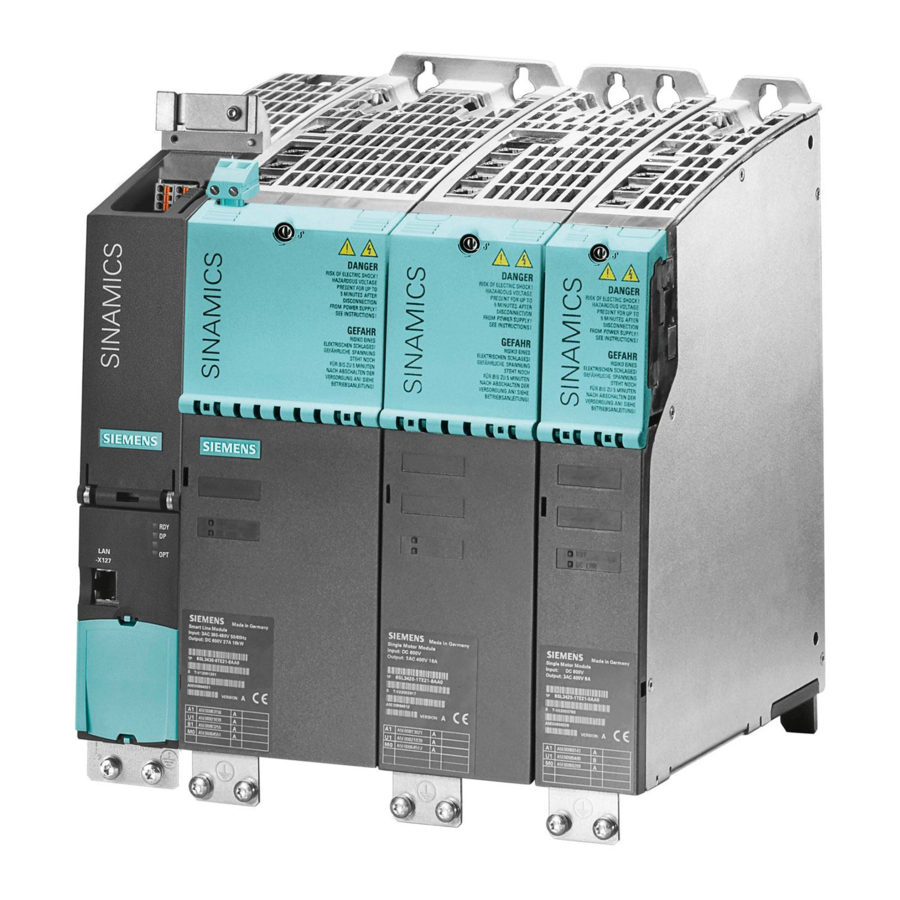
Operation of the PG/PC control panel for driving the motor SINAMICS S120 system overview The SINAMICS S120 drive system consists of a variety of different modules. It is constructed of infeeds, filters, motor power units, modules for additional functions, Control Units plus standard and special versions of rotating and linear motors. - Page 12 All manuals and user guides at all-guides.com SINAMICS S120 drive system 1.2 SINAMICS S120 system overview Getting Started Getting Started, 11/2009, 6SL3097-4AG00-0BP0...
-
Page 13: Requirements
All manuals and user guides at all-guides.com Requirements Requirements Hardware and software components ● A CU320-2 DP Control Unit, firmware version 4.3 SP1 or higher, with integrated PROFIBUS interface ● A Line Module ● A line filter ● A Motor Module ●... -
Page 14: Wiring The Components
Note For information about assembling and wiring the components of the sample project, please refer to the relevant chapters in the SINAMICS S120 Equipment Manual GH2. Getting Started Getting Started, 11/2009, 6SL3097-4AG00-0BP0... -
Page 15: Creating A Drive Project
All manuals and user guides at all-guides.com Creating a drive project This chapter explains how to create a new drive project. You set up a sample project using the STARTER commissioning tool. You then transfer the sample project to the Control Unit of the real drive over a communications interface. - Page 16 All manuals and user guides at all-guides.com Creating a drive project 3.1 Setting the communications interface 3. In the dropdown list "Access Point of the Application", select entry "DRIVES (STARTER, SCOUT) --> CP5511(PROFIBUS)". 4. Click on button "Properties" in order to set the interface. The "Properties - CP5511(PROFIBUS)"...
- Page 17 All manuals and user guides at all-guides.com Creating a drive project 3.1 Setting the communications interface 7. Click on button "Diagnosis" in the "Set PG/PC interface" window. The diagnosis window opens as well. Check the function and settings of the interface in this window.
-
Page 18: Creating A New Drive Project
All manuals and user guides at all-guides.com Creating a drive project 3.2 Creating a new drive project Creating a new drive project The project wizard will guide you through all the steps necessary to create and set up a new drive project. - Page 19 All manuals and user guides at all-guides.com Creating a drive project 3.2 Creating a new drive project 5. Click on "Continue >". The project wizard continues to step 3 to search for drive units. The drive units found are displayed in the preview box. 6.
- Page 20 All manuals and user guides at all-guides.com Creating a drive project 3.2 Creating a new drive project Getting Started Getting Started, 11/2009, 6SL3097-4AG00-0BP0...
-
Page 21: Configuring Your Drive Project
All manuals and user guides at all-guides.com Configuring your drive project Restoring the factory settings In order to restore the drive to a defined state, it is recommended that you reset the drive parameters to their "factory settings" or defaults before the drive is commissioned. Sequence 1. - Page 22 All manuals and user guides at all-guides.com Configuring your drive project 4. Select drive object S120_CU320_2_DP with the right-hand mouse button and select command Target device > Restore factory settings in the context menu. 5. Click on "OK" to confirm the prompt. The PG/PC sets the drive parameters to their factory settings.
-
Page 23: Configuring The Drive Units
All manuals and user guides at all-guides.com Configuring your drive project Configuring the drive units In this chapter, a link is established between the connected drive unit and the S120_CU320_2_DP, and the drive unit is configured for operation. Sequence 1. In the project navigator, click on the "+" symbol before the entry "S120_CU320_2_DP". A list of the drive units in this drive train is displayed. - Page 24 All manuals and user guides at all-guides.com Configuring your drive project The Control Unit searches for connected drive units over the DRIVE-CLiQ interface and finds a drive in the sample project. 4. Select the entry "Servo" from the dropdown list "Default setting for all components". The drive in the sample project will now be controlled as a servo drive.
- Page 25 All manuals and user guides at all-guides.com Configuring your drive project The window for infeed configuring is displayed: 8. Click on button "Wizard..." The window "Configuration - S120_CU320_2_DP - infeed drive object" is displayed. 9. Click "Continue >". The window "Configuration - S120_CU320_2_DP - infeed drive object - additional data" is displayed.
-
Page 26: Configuring The Motor Module
All manuals and user guides at all-guides.com Configuring your drive project 12. Click on "Continue >". The summary view opens. 13. Click "Complete". You will now exit the wizard. 14. In order to transfer the manually changed data to the drive system, select menu command Target system >... -
Page 27: Commissioning A Drive
Virtual START/STOP and JOG keys are provided for operation of the drive, along with various diagnostic functions. References For more information about these functions, refer to the SINAMICS S120 Function Manual. Operation with the virtual control panel 1. Double-click on option "S120_CU320_2_DP >... - Page 28 All manuals and user guides at all-guides.com Commissioning a drive The control panel window is displayed. 2. Click on button "Assume control priority". The "Assume control priority" window opens in addition. 3. Click on button "Safety notes". Getting Started Getting Started, 11/2009, 6SL3097-4AG00-0BP0...
- Page 29 All manuals and user guides at all-guides.com Commissioning a drive Another window containing the safety notes is displayed. 4. Read the notes and then close the window by clicking on the "Close" button. 5. In the "Assume control priority" window, click on button "Accept". The window is closed and the control panel is activated.
- Page 30 All manuals and user guides at all-guides.com Commissioning a drive 8. Enter a suitable speed for the motor in input field "n = ", e.g. 1000. 9. Click on button "I". The motor accelerates to the selected example speed, i.e. to 1000 rpm. 10.
- Page 31 All manuals and user guides at all-guides.com...
- Page 32 All manuals and user guides at all-guides.com Siemens AG Subject to change without prior notice Industry Sector © Siemens AG 2009 Drive Technologies Motion Control Systems P.O. Box 3180 91050 ERLANGEN GERMANY www.siemens.com/motioncontrol...
Need help?
Do you have a question about the SINAMICS S120 and is the answer not in the manual?
Questions and answers