
Related Manuals for Nonin 9847V


Summary of Contents for Nonin 9847V
- Page 1 Operator’s Manual Model 9847V Veterinary Handheld Pulse Oximeter and Carbon Dioxide ) Detector English...
- Page 2 E-mail: infointl@nonin.com nonin.com MPS, Medical Product Service GmbH Borngasse 20 D-35619 Braunfels, Germany References to “Nonin” in this manual shall imply Nonin Medical, Inc. Nonin and PureLight are ® ® registered trademarks or trademarks of Nonin Medical, Inc. Microsoft and Windows registered trademarks of Microsoft Corporation.
-
Page 3: Table Of Contents
No Breath Indicator....................15 Audible Alarm Disabled Indicator ................. 15 Alarm Indicator ..................... 15 Using the 9847V Pulse Oximeter ................16 Connecting the Sensors ..................16 Pulse Oximeter Sensor ..................16 Carbon Dioxide Sensor and Airway Adapter Tube ........... 16 Turn On/Standby .................... - Page 4 Contents (Continued) Calendar and Clock Settings ................23 Visible Indicators ....................23 Display .....................23 Pulse Rate Display ....................23 and Pulse Rate Displays................24 Alarm Limit Review ....................24 Pulse Quality Indicator..................25 No Breath Indicator....................25 Bar Graph ....................25 Low Battery Indicator ..................26 Audible Alarm Disabled Indicator...............27 Audible Indicators ....................27 Breath Beep.......................27 Critically Low Battery Alarm................28...
- Page 5 Contents (Continued) Accessories ......................42 Troubleshooting ...................... 43 Technical Information ..................... 45 Manufacturer’s Declaration................... 45 Equipment Response Time .................. 48 Testing Summary ....................49 Accuracy Testing..................49 Pulse Rate Motion Testing................49 Low Perfusion Testing ..................49 Principles of Operation ..................50 Specifications .......................
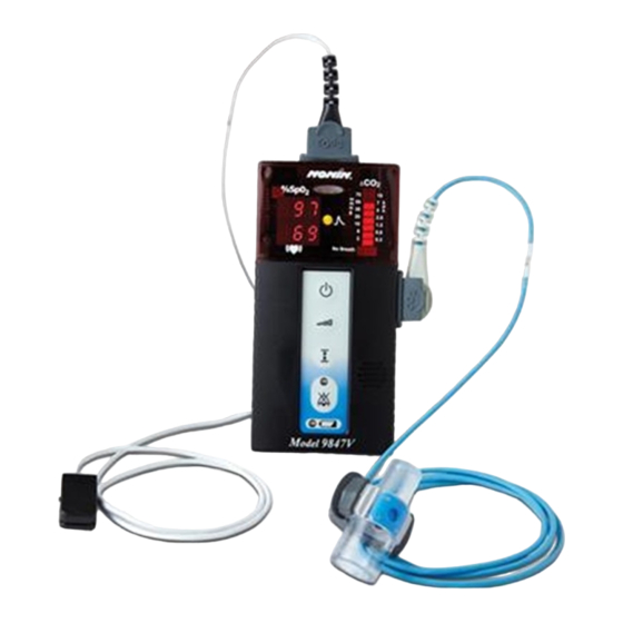
- Page 6 Figures Figure 1. Model 9847V Veterinary Pulse Oximeter and Carbon Dioxide Detector with Alarms ....................... 7 Figure 2. Model 9847V Controls and Indicators............7 Figure 3. Replacing Batteries - Model 9847V ............11 Figure 4. Rear View - Model 9847V................11 Figure 5.
- Page 7 Tables Table 1. Symbols....................... 5 Table 2. Alarm Limit, Breath Beep Pitch, Calendar, and Clock Mode Parameter ... 20 Table 3. Alarm Limits Displayed During an Alarm Limit Review ......24 Table 4. Audible and Visible Indicator Functions During Alarm Conditions .... 29 Table 5.
-
Page 8: Indications For Use
Verify all alarm settings and limits during system startup to ensure that they are set as intended. A hazard can exist if different presets are used on multiple 9847V monitors in one care area. This device should not be used adjacent to or stacked with other equipment. If adjacent or stacked use is necessary, the device should be observed carefully to verify normal operation. -
Page 9: Cautions
Inspect the sensor application site at least every 4 hours to ensure correct sensor alignment and skin integrity. Each animal's sensitivity to Nonin sensors may vary depending on its medical status or the condition of its tissue. Inadequate perfusion, thick fur, foreign matter that blocks light, or an improperly applied sensor can result in erratic and inaccurate oxygen saturation and/or pulse rate measurement. - Page 10 Do not attempt to open the case or repair the electronics. Opening the case may damage the device and void the warranty. Any sign or evidence of opening the system, field service by non-Nonin personnel, tampering, or any kind of misuse or abuse of the system, shall void the warranty in its entirety.
- Page 11 Indications for Use Cautions (Continued) Portable and mobile RF communications equipment can affect medical electrical equipment. Place a dark cloth or surgical drape over the pulse oximeter sensor in order to reduce interference from ambient light. This device is designed to determine the percentage of arterial oxygen saturation of functional hemoglobin. Factors that measurement include the following: may degrade pulse oximeter performance or affect the accuracy of the SpO - excessive ambient light...
-
Page 12: Guide To Symbols
Guide to Symbols Guide to Symbols This table describes the symbols found on the Model 9847V and in this manual. Table 1: Symbols Symbol Description CAUTION! Consult Instructions for Use. Follow Instructions for Use. Type BF Applied Part (Patient isolation from electrical shock). - Page 13 Guide to Symbols Table 1: Symbols (Continued) Symbol Description Front Panel Buttons On/Standby Advance/Breath Beep Volume Control Alarm Limit Review Audible Alarm Disabled Display Indicators Display %SpO Low Battery Indicator Pulse Rate Display Pulse Quality Indicator Change in CO Concentration Absence of CO Detection...
-
Page 14: Introduction
The 9847V will typically operate for 90 hours continuously between battery replacements when used for pulse oximetry alone, or for 20 hours continuously when used for both detection and pulse oximetry. -
Page 15: Audible Alarms And Informational Tones
Introduction Audible Alarms and Informational Tones 9847V uses audible alarms and informational tones (along with visible indicators) to alert veterinary professionals to several animal and equipment conditions. A high priority (animal) alarm alerts the veterinary professional of a animal’s absence of breath, high or low oxygen saturation, pulse rate, or inadequate pulse quality signal. -
Page 16: Carbon Dioxide Detector
Unpacking the Model 9847V Contact the carrier immediately if the shipping carton is damaged. Carefully unpack the device and its accessories. Nonin’s standard package configuration consists of the following items: • 1 Model 9847V Veterinary Pulse Oximeter and CO Detector •... -
Page 17: Batteries
Introduction Batteries 9847V is powered by six AA size alkaline batteries. Approximate battery capacity: • Pulse oximeter (SpO ) only: 90 hours • CO and pulse oximeter: 20 hours • CO only: 24 hours The Low Battery indicator is lit when the battery capacity is low. Replace the batteries as soon as possible. -
Page 18: Figure 3. Replacing Batteries - Model 9847V
Introduction IMPORTANT: Insert these two batteries first. Battery Orientation Battery Door Figure 3: Replacing Batteries - Model 9847V VETERINARY USE ONLY UL 60601-1 Serial Number 30EM NONIN MEDICAL, INC. PLYMOUTH, MN USA MODEL 9847V VETERINARY PULSE OXIMETER/CO2 DETECTOR Battery Orientation... -
Page 19: Important Notes About Battery Use
• Pulse oximeter and CO sensor - 20 hours • The memory of the 9847V may be erased when the batteries are removed. • Replacing batteries may erase the clock settings of the 9847V. • Calendar/clock settings can affect battery storage life. Batteries drain during storage, but they drain more quickly when the unit’s calendar/clock functions are set. -
Page 20: Setting Up The Tabletop Stand
The Model 8500TS Tabletop Stand can be used to place the Model 9847V in a viewable position. Slide the Model 9847V into the stand, then swing the metal leg into position behind the stand to form a solid base. Route the Model UNI-EXT-3 Extension Cable or the pulse oximeter sensor cable through the notch at the bottom edge of the stand (figure 5). -
Page 21: Displays And Indicators
Displays and Indicators Displays and Indicators The following is an overview of the device’s displays and indicators (figure 2). See “Visible Indicators” on page 23 for more detailed information. Display Identified by the %SpO symbol, this 3-digit light-emitting diode (LED) display shows the current oxygen saturation percentage. -
Page 22: No Breath Indicator
Displays and Indicators No Breath Indicator Identified by the No Breath symbol, this LED indicator is a high priority animal alarm. It flashes when breath is not detected for a period of time that exceeds the set no breath delay time. Audible Alarm Disabled Indicator Identified by the symbol, this LED indicator is steadily lit when the audible alarm is permanently... -
Page 23: Using The 9847V Pulse Oximeter
Using the 9847V Pulse Oximeter Using the 9847V Pulse Oximeter Connecting the Sensors Pulse Oximeter Sensor Attach the sensor (with the Nonin logo facing up) to the device (figure 6). Verify the sensor is securely connected. Veterinary Pulse Oximeter Sensor... -
Page 24: Pulse Oximeter Startup
NOTE: The audible alarm disabled indication cannot be turned off until a sensor is plugged in. NOTE: When 9847V is turned on and the alarms are disabled, the yellow Audible Alarm Disabled indicator remains lit. -
Page 25: Event Marker
CO sensor fault. Setup On / Standby Advance / All functions of the 9847V are controlled by buttons found on the Breath Beep keypad on the front of the device. Volume Control Alarm Limit Press On/Standby to turn the device on or to enter Standby mode. -
Page 26: Making Selections In Setup Mode
NOTE: You may exit setup mode at any point and save your current animal alarm limit changes (without stepping through the remainder of the setup mode menu options). 1. Complete the desired selections, then turn off the 9847V. 2. Next, enter setup mode again and choose rCL (recall stored limits) from the alarm mode settings. -
Page 27: Disabling The Audible Alarms
Using the 9847V Pulse Oximeter Table 2: Alarm Limit, Breath Beep Pitch, Calendar, and Clock Mode Parameter Appears in Pulse Rate Display Parameter Default Value Display Range of Values dFt, rCL, C02 Alarm Mode dFt =default limits rCL = recall stored limits... -
Page 28: Setting Parameters
• dFt (default limits) sets up the system-defined (default) animal alarm limit settings. • rCL (recall stored limits) sets up the last stored animal alarm limit settings of the 9847V. • C02 (no breath alarm limits and sensor alarms) temporarily disables the oxygen saturation high and low settings and the pulse rate high and low settings by setting them to 0FF. -
Page 29: No Breath Delay Time Setting
Using the 9847V Pulse Oximeter No Breath Delay Time Setting 1. Upon entering no breath delay time setup, “nbd” appears in the SpO display. The no breath delay time may be set from 15 to 60 (seconds) in increments of 5, or to OFF. -
Page 30: Calendar And Clock Settings
Begin normal operation. Visible Indicators Refer to Figure 2 on page 7 for a detailed illustration of the 9847V controls and indicators. The intended operator’s position for correctly perceiving a visual alarm signal and its priority is 1 meter (3.3 feet), per IEC 60601-1-8. -
Page 31: Spo And Pulse Rate Displays
Using the 9847V Pulse Oximeter and Pulse Rate Displays A pulse oximeter sensor fault occurs if the 9847V pulse oximeter detects a sensor disconnect, dislodgement, or failure. If a pulse oximeter sensor fault occurs or a sensor signal is no longer detected, a medium %SpO 2 priority (equipment) alarm starts. -
Page 32: Pulse Quality Indicator
When a breath is again detected, the visible and audible no breath indicators stop. The no breath delay timer is first started when the CO sensor is plugged into the 9847V and the system is not in setup mode (when the lower bar is lit on the CO display). -
Page 33: Low Battery Indicator
4. Batteries must be replaced. The device will not monitor an animal once the batteries reach a critically low level. The batteries must be replaced before using the 9847V. NOTE: Removing batteries may delete memory and all user defined settings, including calendar... -
Page 34: Audible Alarm Disabled Indicator
Alarm Disabled indicator is steadily lit. If the audible alarms are temporarily disabled, the Audible Alarm Disabled indicator blinks. After the 9847V is turned on (and after exiting the setup mode, if applicable) and until a pulse oximeter or CO sensor is plugged in for the first time, the Audible Alarm Disabled indicator blinks (or remains steadily lit if the audible alarms are permanently disabled). -
Page 35: Critically Low Battery Alarm
The audible critically low battery alarm is a medium priority equipment alarm indicating the batteries have reached a critically low level and must be replaced immediately. The 9847V will not monitor animals after the batteries reach a critical power level. Also during this medium priority alarm, the visible Low Battery indicator blinks. -
Page 36: No Breath Alarm
When a breath is again detected, the audible and visible No Breath indicators stop. The no breath delay timer starts when the CO sensor is connected into the 9847V and the system is not in setup mode (i.e., when the lower bar is lit on the CO bar graph). - Page 37 Using the 9847V Pulse Oximeter Table 4: Audible and Visible Indicator Functions During Alarm Conditions (Continued) Alarm Condition Audible Indication Visible Indication high or low High priority animal alarm SpO numeric display blinking; if latched for critical battery state, displays blinking dashes in all 3 LEDs.
-
Page 38: Description Of Alarm Sounds
(e.g., a critical battery condition could begin while a no breath condition is occurring). Therefore, the 9847V software uses a set of rules to determine the priority of these sounds. These sound control rules are described in Table 5. - Page 39 Using the 9847V Pulse Oximeter Table 5: Audible Indicator Sound Control Priorities (Continued) Condition Sound Control Priorities Audible alarms re-enabled via When the audible alarms are re-enabled, and at least one alarm Audible Alarm Disable button or condition exists, the sound cycle for the highest priority alarm ending of 2-minute disable condition in effect at that time will be started.
-
Page 40: Carbon Dioxide Sensor And Airway Adapter Tube
The Model 9840SA CO Sensor is a crescent-shaped device containing light emitting and detecting elements (figure 7) on the end of a cable that connects to the 9847V. The CO sensor is connected onto the Model 9840AAT Airway Adapter Tube, which in turn is connected between the endotracheal tube and the breathing circuit of an intubated animal. -
Page 41: Airway Adapter Tube
Carbon Dioxide Sensor and Airway Adapter Tube Airway Adapter Tube WARNING: Do not reuse the Model 9840AAT Airway Adapter Tube. Cleaning the interior will damage the anti-fog coating and cause inaccurate readings or a CO sensor alarm. WARNING: The Model 9840AAT Airway Adapter Tube will increase dead space by approximately 6 cubic centimeters (0.4 cubic inches);... -
Page 42: Figure 9. Connecting The Airway Adapter Tube To The Co 2 Sensor
See Figure 10 for an illustration of the configuration. NOTE: Not all tapered connectors are compatible with the airway adapter tube. Ensure all connections are secure. Breathing Circuit (a breathing device, breathing bag, ventilator, etc.) 9847V Model 9840AAT Model 9840SA CO sensor Airway Adapter Tube... -
Page 43: Care And Maintenance
Clean the device separately from the sensors. For instructions on cleaning pulse oximeter sensors, refer to the respective sensor instructions for use. CAUTION: Do not place the Model 9847V in liquid or clean it with agents containing ammonium chloride, isopropyl alcohol, or products that are not listed in this User’s Guide. -
Page 44: Memory Functions
2 pulses per minute from 201 to 300 pulses per minute. NOTE: The 9847V can not store pulse rates greater than 300 pulses per minute in memory. All detected pulse rates greater than 300 pulses per minute are truncated and saved as 300 pulses per minute in memory. - Page 45 Memory Functions Data are played back at a rate of 20 minutes of collected data per second. A 24-hour recording session (the maximum memory saved) is played back in approximately 1 minute. After all data are played back, the device should be shut off before collecting new animal data. The animal information is held in memory as long as the batteries are good, so if the memory must be cleared, remove the batteries for a period of 60 seconds or longer.
-
Page 46: Communications
Communications Communications Real-Time Serial Output The 9847V provides real-time data output capability via the pulse oximeter sensor connector (a 9-pin Sub-D connector). The sensor connector pin assignments are listed in table 6. Table 6: Pulse Oximeter Sensor Connector Pin Assignments... -
Page 47: Connecting The Device Into A Medical System
Communications Connecting the Device into a Medical System Incorporating the device into a medical system requires the integrator to identify, analyze, and evaluate the risks to patient, operators, and third parties. Subsequent changes to the medical system after device integration could introduce new risks and will require additional analysis. Changes to the medical system that must be evaluated include: •... -
Page 48: Service, Support And Warranty
This warranty excludes cost of delivery to and from Nonin. All repaired units shall be received by the purchaser at Nonin's place of business. Nonin reserves the right to charge a fee for a warranty repair request on any unit found to be within specifications. -
Page 49: Accessories
1000USB-C USB Interface Adapter (Continua™) For more information about Nonin parts and accessories contact your distributor, or contact Nonin at (800) 356-8874 (USA and Canada),+1 (763) 553-9968, or +31 (0)13 - 79 99 040 (Europe). WARNING: The use of accessories, sensors, and cables other than those specified may result in increased emission and/or decreased immunity of this device. -
Page 50: Troubleshooting
A non-compatible SpO sensor is Replace sensor with a Nonin- being used. branded Purelight sensor. The middle digits display No SpO signal is detected. Verify sensor connection. - Page 51 Remove device from the EMI performance. environment. Note: If these solutions do not correct the problem with your device, please contact Nonin Technical Service at (800) 356-8874 (USA and Canada), +1 (763) 553-9968, or +31 (0)13 - 79 99 040 (Europe).
-
Page 52: Technical Information
Technical Information Technical Information NOTE: This product complies with ISO 10993-1, Biological Evaluation of Medical Devices Part 1: Evaluation and Testing. CAUTION: A functional tester cannot be used to assess the accuracy of a pulse oximeter monitor or sensor. CAUTION: All parts and accessories connected to the serial port of this device must be certified according to at least IEC Standard EN 60950, IEC 62368-1, or UL 1950 for data-processing equipment. -
Page 53: Table 8. Electromagnetic Immunity
Technical Information Table 8: Electromagnetic Immunity Compliance Electromagnetic Immunity Test IEC 60601 Test Level Level Environment—Guidance This device is intended for use in the electromagnetic environment specified below. The user of this device should ensure that it is used in such an environment. Electrostatic ±6 kV contact ±6 kV contact... -
Page 54: Table 9. Guidance And Manufacturer's Declaration - Electromagnetic Immunity
Technical Information Table 9: Guidance and Manufacturer’s Declaration – Electromagnetic Immunity IEC 60601 Compliance Electromagnetic Environment— Immunity Test Test Level Level Guidance This device is intended for use in the electromagnetic environment specified below. The user of this device should ensure that it is used in such an environment. Portable and mobile RF communications equipment should be used no closer to any part of the device, including cables, than the recommended separation distance calculated from the equation applicable to the frequency of the transmitter. -
Page 55: Equipment Response Time
Technical Information Table 10: Recommended Separation Distances This table details the recommended separation distances between portable and mobile RF communications equipment and this device. This device is intended for use in an electromagnetic environment in which radiated RF disturbances are controlled. -
Page 56: Testing Summary
• The response of the 4-beat average is 1.5 seconds. Testing Summary accuracy, and low perfusion testing was conducted by Nonin Medical, Inc., as described below: Accuracy Testing accuracy testing is conducted during induced hypoxia studies on healthy, non-smoking, light- to dark-skinned human subjects during motion and no-motion conditions in an independent research laboratory. -
Page 57: Principles Of Operation
Technical Information Principles of Operation Pulse oximetry is a non-invasive method that passes red and infrared light through perfused tissue and detects the fluctuating signals caused by arterial pulses. Well-oxygenated blood is bright red, while poorly oxygenated blood is dark red. The pulse oximeter determines functional oxygen saturation of arterial hemoglobin (SpO ) from this color difference by measuring the ratio of absorbed red and infrared light as volume fluctuates with each pulse. - Page 58 Technical Information Temperature (Operating) 0 °C to +40 °C (32 °F to +104 °F) Temperature (Storage/Transportation): -40 °C to +70 °C (-40 °F to +158 °F) Humidity (Operating) 10% to 95% noncondensing Humidity (Storage/Transportation): 10% to 95% noncondensing Altitude (Operating) Up to 3,000 meters (10,000 feet) Altitude (Hyperbaric Pressure): Up to 4 atmospheres Power Requirements...
Need help?
Do you have a question about the 9847V and is the answer not in the manual?
Questions and answers