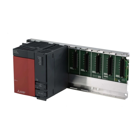
Mitsubishi Q Series User Manual
Positioning module, programmable logic controller
Hide thumbs
Also See for Q Series:
- User manual (244 pages) ,
- Programming manual (194 pages) ,
- Connectivity manual (5 pages)

Related Manuals for Mitsubishi Q Series


Summary of Contents for Mitsubishi Q Series
- Page 1 Type QD70 Positioning Module User's Manual QD70P4 Mitsubishi Programmable QD70P8 Logic Controller GX Configurator-PT (SW1D5C-QPTU-E)
-
Page 2: Safety Instructions
SAFETY INSTRUCTIONS (Always read these instructions before using this equipment.) Before using this product, please read this manual and the relevant manuals introduced in this manual carefully and pay full attention to safety to handle the product correctly. The instructions given in this manual are concerned with this product. For the safety instructions of the programmable logic controller system, please read the CPU module User's Manual. - Page 3 CAUTION Do not bundle or adjacently lay the control wire or communication cable with the main circuit or power wire. Separate these by 100mm (3.94in.) or more. Failure to observe this could lead to malfunctioning caused by noise. [MOUNTING INSTRUCTIONS] CAUTION Use the PLC within the general specifications environment given in this manual.
- Page 4 [STARTUP/MAINTENANCE INSTRUCTIONS] CAUTION Never disassemble or modify the module. Failure to observe this could lead to trouble, malfunctioning, injuries or fires. Always turn all phases of the power supply OFF externally before installing or removing the module. Failure to turn all phases OFF could lead to module trouble or malfunctioning. Before starting test operation, set the parameter speed limit value to the slowest value, and make sure that operation can be stopped immediately if a hazardous state occurs.
-
Page 5: Revisions
This manual confers no industrial property rights or any rights of any other kind, nor does it confer any patent licenses. Mitsubishi Electric Corporation cannot be held responsible for any problems involving industrial property rights which may occur as a result of using the contents noted in this manual. -
Page 6: Table Of Contents
INTRODUCTION Thank you for purchasing the Mitsubishi programmable logic controller MELSEC-Q Series. Always read through this manual, and fully comprehend the functions and performance of the Q Series PLC before starting use to ensure correct usage of this product. CONTENTS SAFETY INSTRUCTIONS..........................A- 1... - Page 7 4 DATA USED FOR POSITIONING CONTROL(LIST OF BUFFER MEMORY ADDRESSES) 4- 1 to 4- 31 4.1 Type of data ............................. 4- 1 4.1.1 Parameters and data required for control..................4- 1 4.1.2 Setting items for parameters......................4- 3 4.1.3 Setting items for OPR data ....................... 4- 4 4.1.4 Setting items for JOG data........................
- Page 8 7.3 Creating a program ..........................7- 5 7.3.1 General configuration of program..................... 7- 5 7.3.2 Positioning control operation program....................7- 6 7.4 Positioning control program examples ....................7- 8 7.5 Program details ............................7- 12 7.5.1 Initialization program ........................7- 12 7.5.2 Start method setting program ......................
- Page 9 App- 1 to App- 18 Appendix 1 External dimension drawing ....................App- 1 Appendix 2 Operation timing and processing time in each control ............App- 2 Appendix 3 Connection examples with servo amplifiers manufactured by MITSUBISHI Electric Corporation ..............................App- 6 Appendix 3.1 Connection example of QD70P and MR-H A............App- 6...
-
Page 10: About Manuals
10H ..16 Hexadecimal Conformation to the EMC Directive and Low Voltage Instruction For details on making Mitsubishi PLC conform to the EMC directive and low voltage instruction when installing it in your product, please refer to Chapter 3, “EMC Directive and Low Voltage Instruction” of the using PLC CPU module User’s Manual (Hardware). -
Page 11: Generic Terms And Abbreviations
Generic Terms and Abbreviations Unless specially noted, the following generic terms and abbreviations are used in this manual. Generic term/abbreviation Details of generic term/abbreviation PLC CPU Generic term for PLC CPU on which QD70 can be mounted. AD75 Generic term for type A1SD75P1-S3/P2-S3/P3-S3, AD75P1-S3/P2-S3/P3-S3 Positioning module. -
Page 12: Section 1 Product Specifications And Handling
SECTION 1 PRODUCT SPECIFICATIONS AND HANDLING Section 1 is configured for the following purposes (1) to (4). (1) To understand the outline of positioning control, and the QD70 specifications and functions (2) To carry out actual work such as installation and wiring (3) To set parameters and data required for positioning control (4) To create a sequence program required for positioning control Read "Section 2"... - Page 13 MEMO...
-
Page 14: Product Outline
1 PRODUCT OUTLINE MELSEC-Q CHAPTER 1 PRODUCT OUTLINE This user's manual provides the specifications, handling, programming methods and other information of the QD70 positioning module used with the MELSEC-Q series CPU module. 1.1 Positioning control 1.1.1 Features of QD70 The following are the features of the QD70. -
Page 15: Mechanism Of Positioning Control
1 PRODUCT OUTLINE MELSEC-Q 1.1.2 Mechanism of positioning control Positioning control using the QD70 is exercised using "pulse signals". (The QD70 is a module that outputs pulses.) In a positioning control system using the QD70, a variety of software and external devices are used to play their roles as shown below. - Page 16 1 PRODUCT OUTLINE MELSEC-Q The principle of "position control" and "speed control" operation is shown below. Position control The total No. of pulses required to move the designated distance is obtained in the following manner. Total No. of pulses No. of pulses Designated distance required to move required for motor to...
-
Page 17: Outline Design Of Positioning Control System
1 PRODUCT OUTLINE MELSEC-Q 1.1.3 Outline design of positioning control system The outline of the positioning control system operation and design, using the QD70, is shown below. (1) Positioning control system using QD70 Positioning module Drive unit PLC CPU Servomotor QD70 Forward run pulse train... - Page 18 1 PRODUCT OUTLINE MELSEC-Q (b) Pulse train output from the QD70 1) As shown in Fig. 1.3, the pulse frequency increases as the servo motor accelerates. The pulses are sparse when the servo motor starts and more frequent when the servo motor speed comes close to the target speed.
- Page 19 1 PRODUCT OUTLINE MELSEC-Q In the system shown in Fig. 1.4, the movement amount per pulse, command pulse frequency, and the deviation counter droop pulser amount are determined as follows: 1) Movement amount per pulse The movement amount per pulse is determined by the worm gear lead, deceleration ratio, and the No.
-
Page 20: Communicating Signals Between Qd70 And Each Module
1 PRODUCT OUTLINE MELSEC-Q 1.1.4 Communicating signals between QD70 and each module The outline of the signal communication between the QD70 (positioning module) and PLC CPU, peripheral device (GX Configurator-PT) and drive unit, etc., is shown below. (A peripheral device communicates with the QD70 via the PLC CPU to which it is connected) Refer to Chapter 3 for details of the I/O signals. - Page 21 1 PRODUCT OUTLINE MELSEC-Q QD70 PLC CPU The QD70 and PLC CPU communicate the following data via the base unit. Direction QD70 PLC CPU PLC CPU QD70 Communication Signal indication QD70 state. Signal related to commands. • Module READY (X0) •...
-
Page 22: Positioning Control
1 PRODUCT OUTLINE MELSEC-Q 1.2 Positioning control 1.2.1 Outline of starting The outline for starting each control is shown with the following flowchart. It is assumed that each module is installed, and the required system configuration, etc., has been prepared. Flow of starting Installation and connection of module Preparation... -
Page 23: Outline Of Stopping
1 PRODUCT OUTLINE MELSEC-Q 1.2.2 Outline of stopping The possible causes of a control stop are as follows. (1) Control ended normally (2) An error occurred in the PLC CPU (3) An error occurred in the QD70 (4) The axis stop signal from the PLC CPU turned ON Stop processings performed in the above cases are outlined in the following table. -
Page 24: System Configuration
2 SYSTEM CONFIGURATION MELSEC-Q CHAPTER 2 SYSTEM CONFIGURATION This chapter explains the system configuration of the QD70. 2.1 General image of system The following is the general configuration including the QD70, PLC CPU, peripheral device and others. (The numbers in the sketch correspond to the "Nos." in the table in "Section 2.2 Component list"... -
Page 25: Component List
2 SYSTEM CONFIGURATION MELSEC-Q 2.2 Component list A positioning system using the QD70 consists of the following components. Product Type Remarks QD70P QD70P4 No. of control axes Positioning module QD70P8 Open collector output type GX Developer SW D5C-GPPW-E For details, refer to the GX Developer Operating Manual and "CHAPTER 6 UTILITY PACKAGE (GX Configurator-PT)". -
Page 26: Applicable System
2 SYSTEM CONFIGURATION MELSEC-Q 2.3 Applicable system The QD70 is usable with the following system. (1) Applicable module and the number of modules that can be installed The following are the CPU module and network module (for remote I/O stations) in which the QD70 can be installed and the number of modules that can be installed. -
Page 27: How To Check The Function Version And The Software Version
2 SYSTEM CONFIGURATION MELSEC-Q 2.4 How to check the function version and the software version The function version of the QD70 and the software version of the GX Configurator-PT can be checked in the following methods. [1] How to check the function version of the QD70 (a) Method using the rated plate on the module side face Check the alphabet at the end of "SERIAL". - Page 28 2 SYSTEM CONFIGURATION MELSEC-Q [2] How to check the software version of the GX Configurator-PT Check the "Product information" displayed on "Help" of GX Developer. [Operation of GX Developer] Choose [Help] Product information <GX Developer display screen> Software version 2 - 5 2 - 5...
-
Page 29: Specifications And Functions
3 SPECIFICATIONS AND FUNCTIONS MELSEC-Q CHAPTER 3 SPECIFICATIONS AND FUNCTIONS This chapter describes the performance specifications of the QD70 and the specifications of the I/O signals transferred to/from the PLC CPU and external device. For the general specifications of the QD70, refer to the user's manual (hardware) of the CPU module used. -
Page 30: List Of Functions
3 SPECIFICATIONS AND FUNCTIONS MELSEC-Q 3.2 List of functions The following table lists the functions of the QD70. (Read "SECTION 2 CONTROL DETAILS AND SETTING" for details of the functions.) Function name Description Reference Mechanically establishes the positioning control start Section Machine OPR control point using a near-point dog or stopper. - Page 31 3 SPECIFICATIONS AND FUNCTIONS MELSEC-Q With the "positioning control", whether or not to continuously execute the positioning data can be set with the "operation pattern". Outlines of the "operation patterns" are given below. Da.1 Operation pattern Description Reference When "Positioning termination" is set for the operation pattern Positioning termination of the started positioning data, only the designated positioning data will be executed, and then the positioning control will end.
-
Page 32: Specifications Of Input/Output Signal With Plc Cpu
3 SPECIFICATIONS AND FUNCTIONS MELSEC-Q 3.3 Specifications of input/output signal with PLC CPU 3.3.1 List of input/output signals with PLC CPU The QD70 uses 32 input points and 32 output points for exchanging data with the PLC CPU. The input/output signals when the QD70 is mounted in slot No. 0 of the main base unit are shown below. -
Page 33: Details Of Input Signal
3 SPECIFICATIONS AND FUNCTIONS MELSEC-Q 3.3.2 Details of input signal (QD70 PLC CPU) The ON/OFF timing and conditions of the input signals are shown below. Device Signal name Description • When the PLC READY signal [Y0] turns from OFF to ON, the parameter and the Module READY ON: Prepared OFF: Not... - Page 34 3 SPECIFICATIONS AND FUNCTIONS MELSEC-Q 3.3.3 Details of output signals (PLC CPU QD70) The ON/OFF timing and conditions of the output signals are shown below. Device No. Signal name Description PLC READY OFF: (a) This signal notifies the QD70 that the PLC CPU is normal. •...
-
Page 35: Specifications Of Input/Output Interfaces With External Device
3 SPECIFICATIONS AND FUNCTIONS MELSEC-Q 3.4 Specifications of input/output interfaces with external device 3.4.1 Electrical specifications of input/output signals Input specifications Rated input Working voltage ON voltage/ OFF voltage/ Signal name Input resistance Response time voltage/current range current current 2.7VDC or more/ 1.0VDC or less/ Ω... - Page 36 3 SPECIFICATIONS AND FUNCTIONS MELSEC-Q : Pulse rising/falling edge time (Unit for "tr" and "tf": µs, unit for "Duty": %) ... When ambient temperature is room temperature. Load voltage (V) 26.4 Cable length (m) Load current Pulse speed Duty Duty (mA) (kpps) (Rising edge)
-
Page 37: Signal Layout For External Device Connection Connector
3 SPECIFICATIONS AND FUNCTIONS MELSEC-Q 3.4.2 Signal layout for external device connection connector The specifications of the connector section, which is the input/output interface for the QD70 and external device, are shown below. The signal layout for the QD70 external device connection connector is shown. QD70P4 QD70P8 ERR. -
Page 38: List Of Input/Output Signal Details
3 SPECIFICATIONS AND FUNCTIONS MELSEC-Q 3.4.3 List of input/output signal details The details of each QD70 external device connection connector are shown below: Signal details Signal name Pin No. Symbol (Negative logic is selected by I/O signal logic selection) • This signal is used for detecting the near-point dog during OPR control. •... -
Page 39: Input/Output Interface Internal Circuit
3 SPECIFICATIONS AND FUNCTIONS MELSEC-Q 3.4.4 Input/output interface internal circuit Shows summary image of the internal circuit of the interface for connection to external devices of the QD70. (For QD70P4, axis 1). Input/output External wiring Pin No. Internal circuit Signal name class Near-point dog signal DOG1... -
Page 40: Data Used For Positioning Control(List Of Buffer Memory Addresses)
4 DATA USED FOR POSITIONING CONTROL MELSEC-Q CHAPTER 4 DATA USED FOR POSITIONING CONTROL This chapter explains the specifications of the data to be set to the QD70. 4.1 Type of data 4.1.1 Parameters and data required for control The parameters and data required to carry out control with the QD70 include the "setting data", "monitor data"... - Page 41 4 DATA USED FOR POSITIONING CONTROL MELSEC-Q Monitor data Data related to the operations of the running axes, e.g. the current positions Axis monitor data and speeds, are monitored. (Storage destination: QD70 buffer memory) ( Md. 1 to Md. 9 ) The error status and warning status of the QD70 are monitored.
-
Page 42: Setting Items For Parameters
4 DATA USED FOR POSITIONING CONTROL MELSEC-Q 4.1.2 Setting items for parameters The table below lists items set to the positioning parameters. Setting of parameters is similarly done for individual axes for all controls achieved by the QD70. For details of controls, refer to SECTION 2 "CONTROL DETAILS AND SETTING". For details of setting items, refer to "4.2 List of parameters". -
Page 43: Setting Items For Opr Data
4 DATA USED FOR POSITIONING CONTROL MELSEC-Q 4.1.3 Setting items for OPR data When carrying out "OPR control", the "OPR data" must be set. The setting items for the "OPR data" are shown below. The "OPR data" are set commonly for each axis. Refer to "Chapter 8 OPR CONTROL"... -
Page 44: Setting Items For Jog Data
4 DATA USED FOR POSITIONING CONTROL MELSEC-Q 4.1.4 Setting items for JOG data The "JOG data" must be set to perform "JOG operation". The following are the setting items of the "JOG data". The "JOG data" are set commonly for each axis. Refer to "CHAPTER 10 JOG OPERATION"... -
Page 45: Setting Items For Positioning Data
4 DATA USED FOR POSITIONING CONTROL MELSEC-Q 4.1.5 Setting items for positioning data Positioning data must be set for carrying out any "positioning control". The table below lists the items to be set for producing the positioning data. 1 to 10 positioning data items can be set for each axis. For details of the positioning controls, refer to "Chapter 9 POSITIONING CONTROL". -
Page 46: Type And Roles Of Monitor Data
4 DATA USED FOR POSITIONING CONTROL MELSEC-Q 4.1.6 Type and roles of monitor data The monitor data area in the buffer memory stores data relating to the control state of the positioning control system, which are monitored as required while the positioning system is operating. -
Page 47: Type And Roles Of Control Data
4 DATA USED FOR POSITIONING CONTROL MELSEC-Q 4.1.7 Type and roles of control data Operation of the positioning control system is achieved through the execution of necessary controls. (Data required for controls are given through the default values when the power is switched ON, which can be modified as required by the sequence program.) Controls are performed over system data or machine operation. -
Page 48: List Of Parameters
4 DATA USED FOR POSITIONING CONTROL MELSEC-Q 4.2 List of parameters Setting value buffer memory address Setting value, setting Item Default value range Axis 1 Axis 2 Axis 3 Axis 4 Axis 5 Axis 6 Axis 7 Axis 8 Pr. 1 Software stroke limit upper 2147483647 limit value -2147483648 to... - Page 49 4 DATA USED FOR POSITIONING CONTROL MELSEC-Q Pr. 4 Current feed value during speed control Specify whether you wish to enable or disable the update of " Md. 1 Current feed value" while operations are performed under the speed control (including the speed-position and position-speed switching control).
- Page 50 4 DATA USED FOR POSITIONING CONTROL MELSEC-Q Pr. 7 Positioning complete signal output time Set the output time of the positioning complete signal [X8 to XF] output from the QD70. Positioning complete indicates that the preset dwell time has elapsed after the QD70 ended pulse output.
- Page 51 4 DATA USED FOR POSITIONING CONTROL MELSEC-Q Pr. 9 PULSE/SIGN method selection setup/hold time Set the setup/hold time when PULSE/SIGN is selected in the pulse output mode to output inverted pulses. 0: 10µs 1: 100µs 2: 1ms 3: 2ms The following is an example for negative logic. PULSE Set in Set in...
- Page 52 4 DATA USED FOR POSITIONING CONTROL MELSEC-Q Pr. 10 Stop mode during path control Set the stopping method using the axis stop signal input when the operation pattern for position control is continuous path control. 0: Position match stop ..Deceleration starts when the axis stop signal is input, and the axis stops immediately when the address preset to the positioning data in execution is reached.
-
Page 53: List Of Opr Data
4 DATA USED FOR POSITIONING CONTROL MELSEC-Q 4.3 List of OPR data Setting value buffer memory address Setting value, setting Item Default value range Axis 1 Axis 2 Axis 3 Axis 4 Axis 5 Axis 6 Axis 7 Axis 8 0: Near-point dog method 1: Stopper 1... - Page 54 4 DATA USED FOR POSITIONING CONTROL MELSEC-Q OPR method 0 : Near-point dog method (1) Start machine OPR control. (Start movement at the " OPR. 4 OPR speed" in the OPR. 4 OPR speed " OPR. 2 OPR direction".) OPR. 5 Creep speed (2) Detect the near-point dog ON, and start deceleration.
- Page 55 4 DATA USED FOR POSITIONING CONTROL MELSEC-Q 3 : Stopper 3 (1) Start machine OPR control. (Start movement at the " OPR. 5 Creep speed" in the " OPR. 2 OPR direction". (At this time, a torque limit is OPR. 5 Creep speed Stopped by stopper needed for the motor.
- Page 56 4 DATA USED FOR POSITIONING CONTROL MELSEC-Q OPR. 2 OPR direction Set the direction to start movement when starting machine OPR control. 0: Forward direction Moves in the direction that the address increments. (Arrow 2)) 1: Reverse direction Moves in the direction that the address decrements. (Arrow 1)) Normally, the OP is set near the lower limit or the upper limit, so "OPR.
- Page 57 4 DATA USED FOR POSITIONING CONTROL MELSEC-Q OPR. 5 Creep speed Set the creep speed after near-point dog ON (the low speed just before stopping after decelerating from the OPR speed). The creep speed is set within the following range. ( OPR.
- Page 58 4 DATA USED FOR POSITIONING CONTROL MELSEC-Q OPR. 7 DEC/STOP time at OPR Set the time taken to make a stop after reaching " Pr. 6 Bias speed at start" from " OPR. 5 Creep speed" under "Count 2" OPR control or to make a stop after reaching "...
-
Page 59: List Of Jog Data
4 DATA USED FOR POSITIONING CONTROL MELSEC-Q 4.4 List of JOG data Setting value buffer memory address Setting value, setting Item Default value range Axis 1 Axis 2 Axis 3 Axis 4 Axis 5 Axis 6 Axis 7 Axis 8 JOG. -
Page 60: List Of Positioning Data
4 DATA USED FOR POSITIONING CONTROL MELSEC-Q 4.5 List of positioning data Before explaining the positioning data setting items Da. 1 to Da. 7 , the configuration of the positioning data will be shown below. The positioning data stored in the QD70 buffer memory has the following type of configuration. - Page 61 4 DATA USED FOR POSITIONING CONTROL MELSEC-Q Positioning data No. Positioning data No. 1290 1390 1280 1380 1220 1320 1210 1310 Da. 1 Operation pattern 1200 Da. 1 Operation pattern 1300 1291 1391 1281 1381 1221 1321 1211 1311 Da. 2 Control method 1201 1301 Da.
- Page 62 4 DATA USED FOR POSITIONING CONTROL MELSEC-Q Setting value buffer memory address Setting value, Item Default value setting range Axis 1 Axis 2 Axis 3 Axis 4 Axis 5 Axis 6 Axis 7 Axis 8 0: Positioning termination 1: Continuous Da.
- Page 63 4 DATA USED FOR POSITIONING CONTROL MELSEC-Q Da. 2 Control method Set the "control method" for positioning control. 0: No control method 1: 1-axis linear control (ABS) 2: 1-axis linear control (INC) 3: Speed.Position Ctrl. (Forward) ..Speed-position switching control (forward run) 4: Speed.Position Ctrl.
- Page 64 4 DATA USED FOR POSITIONING CONTROL MELSEC-Q [" Da. 1 Operation pattern" is "2: Continuous path control"] Da. 3 ACC/DEC time : Set the time taken to reach " Da. 5 Command speed" set in the "positioning data to be executed next" from "...
- Page 65 4 DATA USED FOR POSITIONING CONTROL MELSEC-Q (2) 1-axis linear control (INC) Set a signed movement amount as the setting value (movement amount) for 1- axis linear control (INC). When the movement amount is positive: The axis moves in the positive direction (address increasing direction).
-
Page 66: List Of Monitor Data
4 DATA USED FOR POSITIONING CONTROL MELSEC-Q 4.6 List of monitor data 4.6.1 Axis monitor data Storage buffer memory address Default Item Storage details value Axis 1 Axis 2 Axis 3 Axis 4 Axis 5 Axis 6 Axis 7 Axis 8 •... - Page 67 4 DATA USED FOR POSITIONING CONTROL MELSEC-Q Storage buffer memory address Default Item Storage details value Axis 1 Axis 2 Axis 3 Axis 4 Axis 5 Axis 6 Axis 7 Axis 8 At axis warning occurrence, the warning code corresponding to the warning definition is stored. •...
-
Page 68: Module Information Monitor Data
4 DATA USED FOR POSITIONING CONTROL MELSEC-Q 4.6.2 Module information monitor data Storage buffer memory address Item Storage details Default value (Common for axis 1 to axis 8) At error occurrence, the bit corresponding to the error occurrence axis turns ON. 0: Normal (OFF) 1: Error (ON) (The error occurrence axis cannot be run) -
Page 69: List Of Control Data
4 DATA USED FOR POSITIONING CONTROL MELSEC-Q 4.7 List of control data 4.7.1 Axis control data Setting buffer memory address Default Item Setting details value Axis 1 Axis 2 Axis 3 Axis 4 Axis 5 Axis 6 Axis 7 Axis 8 By setting "1", the following operation is performed. - Page 70 4 DATA USED FOR POSITIONING CONTROL MELSEC-Q Setting buffer memory address Default Item Setting details value Axis 1 Axis 2 Axis 3 Axis 4 Axis 5 Axis 6 Axis 7 Axis 8 Set "1" to request speed change processing (make the " Cd. 7 New speed value" value valid) Cd.
-
Page 71: Setup And Procedures Before Operation
5 SETUP AND PROCEDURES BEFORE OPERATION MELSEC-Q CHAPTER 5 SETUP AND PROCEDURES BEFORE OPERATION This chapter describes the procedure up to the operation of the QD70 and the part identification nomenclature and setting and wiring methods of the QD70. 5.1 Handling precautions This section provides the precautions for handling the QD70. - Page 72 5 SETUP AND PROCEDURES BEFORE OPERATION MELSEC-Q CAUTION Never disassemble or modify the module. Failure to observe this could lead to trouble, malfunctioning, injuries or fires. Always turn all phases of the power supply OFF externally before installing or removing the module.
-
Page 73: Procedures Before Operation
5 SETUP AND PROCEDURES BEFORE OPERATION MELSEC-Q 5.2 Procedures before operation This section gives the procedure up to the operation of the QD70. Start Module installation Install the QD70 in the specified slot. Wiring Wire the external device to the QD70. (Refer to Section 5.4.) Intelligent function module switch setting Make setting using GX Developer. -
Page 74: Part Identification Nomenclature
5 SETUP AND PROCEDURES BEFORE OPERATION MELSEC-Q 5.3 Part identification nomenclature (1) The following are the part names of the QD70. 1) RUN indicator LED, ERR. indicator LED QD70P8 2) Axis display LED ERR. QD70P8 CON2 CON1 3) External device connection connector (40 pins) *For details, refer to "Section 3.4.2 Signal layout for external device connection connector"... - Page 75 5 SETUP AND PROCEDURES BEFORE OPERATION MELSEC-Q (2) The LED display indicates the following operation statuses of the QD70 and axes. QD70P8 ERR. Display Attention point Description Display Attention point Description RUN is OFF. The axes are ERR. and AX1 Hardware AX1 to AX8 are stopped or on...
- Page 76 5 SETUP AND PROCEDURES BEFORE OPERATION MELSEC-Q External device connection connector The connectors for use with the QD70 should be purchased separately by the user. The connector types and pressure displacement tool are listed below. (a) Connector types Type Model name Soldering type, straight out A6CON1 Pressure displacement type, straight out...
-
Page 77: Wiring
5 SETUP AND PROCEDURES BEFORE OPERATION MELSEC-Q 5.4 Wiring This section explains how to wire the drive unit and mechanical system inputs to the QD70. The following are the precautions for wiring the QD70. Read these precautions together with "Section 5.1 Handling precautions" to ensure work safety. 5.4.1 Wiring precautions (1) Always confirm the terminal layout before connecting the wires to the QD70. - Page 78 5 SETUP AND PROCEDURES BEFORE OPERATION MELSEC-Q [Wiring example using shielded cables] The following are wiring examples for noise reduction. Connector Connector (A6CON1/A6CON2) To external Shielded devices cable Drive unit To external device To drive units Use the shortest posible ingth to To QD70 graound the 2mm or more FG wire.
- Page 79 5 SETUP AND PROCEDURES BEFORE OPERATION MELSEC-Q Assembling of connector (A6CON1/A6CON2) Wrap the coated parts with a heat contractile tube. 5 - 9 5 - 9...
- Page 80 (10) To comply with the EMC Directive and Low-Voltage Directive, always ground the QD70 to the control box using the shielded cables and AD75CK cable clamping (Mitsubishi Electric make). Inside control box 20cm (7.88 inch) to 30cm (11.82 inch)
- Page 81 5 SETUP AND PROCEDURES BEFORE OPERATION MELSEC-Q [Wiring examples using duct (improper example and improved example)] Wiring duct Relay Relay Drive Drive Relay unit unit Control box The deive units are placed PLC CPU near the noise source. The connection cable between Noise source the QD70 and drive units is (Power system,...
-
Page 82: Confirming The Wiring
5 SETUP AND PROCEDURES BEFORE OPERATION MELSEC-Q 5.5 Confirming the wiring 5.5.1 Confirmation items at completion of wiring Check the following points when completed with the QD70 installation and wiring. • Is the module correctly wired? ......."Connection confirmation" By making "connection conformation", you can check whether the "QD70 recognizes the external I/O signals such as the near-point dog and speed-position switching signals", for example. - Page 83 5 SETUP AND PROCEDURES BEFORE OPERATION MELSEC-Q (2) Method using GX Configurator-PT Monitor the external I/O signal states on the "Monitor/Test screen". (For details, refer to "Section 6.6 Monitor/test".) (Example) Checking the external I/O signals of Axis 1 (1 Axis OPR Monitor) <GX Configurator-PT display screen>...
-
Page 84: Switch Setting For Intelligent Function Module
5 SETUP AND PROCEDURES BEFORE OPERATION MELSEC-Q 5.6 Switch setting for intelligent function module By making the intelligent function module switch setting, the QD70 allows you to set the pulse output mode, external I/O signal logic and rotation direction. (However, you cannot set the speed-position switching signal (CHG) logic. - Page 85 5 SETUP AND PROCEDURES BEFORE OPERATION MELSEC-Q [Switch 1] Pulse output mode Set the pulse output mode that matches the drive unit used. Use "Switch 2" to change between the positive logic and negative logic of the pulse. The following are pulse output mode examples. (1) CW/CCW mode During forward run, the forward run feed pulse (CW) will be output.
- Page 86 5 SETUP AND PROCEDURES BEFORE OPERATION MELSEC-Q [Switch 3] Zero signal input logic selection, rotation direction setting <Zero signal input logic selection> Set the zero signal (PG0) input logic according to the externally connected device. <Rotation direction setting> Set the relation of the motor rotation direction and current value address increment/decrement.
- Page 87 5 SETUP AND PROCEDURES BEFORE OPERATION MELSEC-Q Operating procedure Using GX Developer, make settings starting with the QCPU PLC parameter "I/O assignment setting" screen. (a) I/O assignment setting screen Specify the following for the slot where the QD70 is mounted. Type : Select "Intelli."...
-
Page 88: Simple Reciprocating Operation
5 SETUP AND PROCEDURES BEFORE OPERATION MELSEC-Q 5.7 Simple reciprocating operation Before operating the system, check the operation of the drive unit. (Make this check after making sure that the installation, wiring, intelligent function module switch setting and connection confirmation of the QD70 are normal. For details of the drive unit, refer to the manual of the drive unit used.) The following is the way to perform "simple reciprocating operation". - Page 89 5 SETUP AND PROCEDURES BEFORE OPERATION MELSEC-Q Reciprocating operation program using JOG operation JOG speed 5000pulse/s JOG ACC/DEC time 1000ms X28 : Forward run JOG command, X29 : Reverse run JOG command 5 - 19 5 - 19...
- Page 90 5 SETUP AND PROCEDURES BEFORE OPERATION MELSEC-Q (4) Confirming the operation status (a) Method using GX Developer Read the following axis monitor data with the monitor function (Buffer memory batch). Buffer memory address Axis monitor data Monitor details Axis 1 Axis 2 Axis 3 Axis 4 Axis 5 Axis 6 Axis 7 Axis 8 Md.
-
Page 91: Utility Package(Gx Configurator-Pt)
6 UTILITY PACKAGE (GX Configurator-PT) MELSEC-Q CHAPTER 6 UTILITY PACKAGE (GX Configurator-PT) The QD70 utility package (GX Configurator-PT) is software designed to make initial setting, auto refresh setting, monitor and others of the QD70 using dedicated screens, without being conscious of the I/O signals and buffer memory. Use the utility package with GX Developer (SW4D5C-GPPW-E or later). -
Page 92: Installing And Uninstalling The Utility Package
6 UTILITY PACKAGE (GX Configurator-PT) MELSEC-Q 6.2 Installing and uninstalling the utility package For installing and uninstalling the utility package (SW0D5C-QCTU-E), see the GPP Function Software for Windows SW4D5C-GPPW-E (V) Operating Manual (Startup). 6.2.1 User precautions The following explains the precautions on using the Utility package: (1) Important safety information Since the utility is add-in software for GX Developer, make sure to read "Safety Precautions"... - Page 93 6 UTILITY PACKAGE (GX Configurator-PT) MELSEC-Q (6) About the number of parameters that can be set in GX Configurator-PT The number of parameters that can be set by the GX Configurator for an intelligent function module installed in the CPU module and in a remote I/O station of the MELSECNET/H network system is limited.
-
Page 94: Operating Environment
6 UTILITY PACKAGE (GX Configurator-PT) MELSEC-Q 6.2.2 Operating environment This section explains the operating environment of GX Configurator-PT. Item Peripheral devices Installation (Add-in) destination Add-in to GX Developer Version4 (English language version) or later ® Pentium (133 MHz or faster recommended) based personal Computer main unit ®... -
Page 95: Explanation Of Utility Package Operations
6 UTILITY PACKAGE (GX Configurator-PT) MELSEC-Q 6.3 Explanation of utility package operations 6.3.1 How to perform common utility package operations (1) Available control keys Special keys that can be used during operations of the utility package and their applications are shown in the table below. Name of key Application Cancels a newly entered value when entering data in a cell. - Page 96 6 UTILITY PACKAGE (GX Configurator-PT) MELSEC-Q 3) Operating using GX Developer. [Online] [Read from PLC] / [Write to PLC] "Intelligent module parameter" Or, operate on the intelligent module parameter setting module selection screen of the utility. [Online] [Read from PLC] / [Write to PLC] <Text file>...
-
Page 97: Operation Overview
6 UTILITY PACKAGE (GX Configurator-PT) MELSEC-Q 6.3.2 Operation overview GX Developer screen [Tools] - [Intelligent function utility] - [Start] Intelligent function module parameter setting module select Enter "Start I/O No." then select "Package name" and "Module model neme". Refer to Section 6. 3. 3 Initial setting Auto refresh Initial setting screen... - Page 98 6 UTILITY PACKAGE (GX Configurator-PT) MELSEC-Q [Online] - [Monitor/test] Select monitor/test module screen Enter "Start I/O No." then select" Package name" Monitor/test and "Module model neme". Monitor/Test screen Refer to Section 6. 6 6 - 8 6 - 8...
-
Page 99: Starting The Intelligent Function Module Utility
6 UTILITY PACKAGE (GX Configurator-PT) MELSEC-Q 6.3.3 Starting the intelligent function module utility [Purpose of operation] Start the utility from GX Developer, and display the intelligent module parameter setting module selection screen. The initial setting, auto refresh setting and select monitor/test module (selecting the module for which monitoring/testing is to be performed) screens can be started from this screen. - Page 100 6 UTILITY PACKAGE (GX Configurator-PT) MELSEC-Q (3) Menu bar (a) File items File operations are performed for the intelligent module parameters for the project opened by GX Developer. [Open file] : Opens the parameter file. [Close file] : Closes the parameter file. If changes have been made, the dialog box asking whether to save the file appears.
-
Page 101: Initial Setting
6 UTILITY PACKAGE (GX Configurator-PT) MELSEC-Q 6.4 Initial setting [Purpose of operation] Make initial setting axis-by-axis for the QD70 to operate. The following items are data that need initial setting. • Parameters • OPR data • Positioning data This initial setting makes sequence program setting unnecessary. For more information on the setting details, refer to "CHAPTER 4 DATA USED FOR POSITIONING CONTROL". - Page 102 6 UTILITY PACKAGE (GX Configurator-PT) MELSEC-Q <Initial setting of positioning data> Move to sub window Axis #1 Positioning Setting Select items to be moved to sub window. [Explanation of items] (1) Setting item list Setting item Axis #1 Parameter Setting Axis #1 OPR data Setting n indicates the axis No.
-
Page 103: Auto Refresh Setting
6 UTILITY PACKAGE (GX Configurator-PT) MELSEC-Q 6.5 Auto refresh setting [Purpose of operation] Set the QD70 buffer memory to be automatically refreshed. There are the following setting items as the auto refresh setting parameters. [Common to all axes] • Error status •... - Page 104 6 UTILITY PACKAGE (GX Configurator-PT) MELSEC-Q [Explanation of items] (1) Setting item list Setting item Error status Warning status Axis #1 Current Feed Value Axis #1 Current Speed Axis #1 Axis Operation Status Axis #1 Axis Error Code Axis #1 Axis Warning Code n indicates the axis No.
-
Page 105: Monitor/Test
6 UTILITY PACKAGE (GX Configurator-PT) MELSEC-Q 6.6 Monitor/test 6.6.1 Monitor/Test screen [Purpose of operation] Start the buffer memory monitoring/testing, and I/O signals monitoring/testing from this screen. (Refer to "Section 4.6 List of monitor data" for details of monitor data.) [Startup procedure] Select monitor/test module screen "Start I/O No. - Page 106 6 UTILITY PACKAGE (GX Configurator-PT) MELSEC-Q <X/Y Monitor> Move to sub window X/Y Monitor Select items to be moved to sub window. [Explanation of items] (1) Setting item list Setting item Module READY PLC READY Axis Error Occurrence Axis Warning Occurrence Axis #1 BUSY Axis #n BUSY Axis #1 Error Status...
- Page 107 6 UTILITY PACKAGE (GX Configurator-PT) MELSEC-Q (3) Explanation of the command buttons Displays the current value of the selected item. Current value display (This command button is used to check text that cannot be displayed in the current value field. However, in this utility package, all items can be displayed in the display fields).
-
Page 108: Sequence Program Used For Positioning Control
7 SEQUENCE PROGRAM USED FOR POSITIONING CONTROL MELSEC-Q CHAPTER 7 SEQUENCE PROGRAM USED FOR POSITIONING CONTROL This chapter describes sequence programs of the positioning control system using the QD70. 7.1 Precautions for creating program (1) System configuration Unless otherwise specified in this section and later, the sequence programs shown are those for the following system. - Page 109 7 SEQUENCE PROGRAM USED FOR POSITIONING CONTROL MELSEC-Q (c) When the circuit uses the "intelligent function device" for a COMPARISON command, change the command to a FROM command and a COMPARISON command. FROMP D102 Data read out D102 (d) When the circuit uses the "intelligent function device" for a WAND command, change the command to a FROM command and a WAND command.
-
Page 110: List Of Devices Used
7 SEQUENCE PROGRAM USED FOR POSITIONING CONTROL MELSEC-Q 7.2 List of devices used In "Section 7.4 Positioning control program examples", the used devices are assigned as indicated in the following table. The I/O numbers for QD70 indicate those when QD70 is mounted in the 0-slot of the main base. - Page 111 7 SEQUENCE PROGRAM USED FOR POSITIONING CONTROL MELSEC-Q (2) Data registers (for Axis 1) Device name Device Data stored Setting value ( Pr. 1 Software stroke limit upper limit value) 100000000pulse ( Pr. 2 Software stroke limit lower limit value) -100000000pulse ( Pr.
-
Page 112: Creating A Program
7 SEQUENCE PROGRAM USED FOR POSITIONING CONTROL MELSEC-Q 7.3 Creating a program This section explains "positioning control operation programs" actually used. The programs designed to perform the functions described in "SECTION 2 CONTROL DETAILS AND SETTING" are installed in the "positioning control operation programs" explained in “Section 7.3.2”. -
Page 113: Positioning Control Operation Program
7 SEQUENCE PROGRAM USED FOR POSITIONING CONTROL MELSEC-Q 7.3.2 Positioning control operation program The following are individual programs which comprise the "positioning control operation programs". When creating a program, refer to the explanation item of the corresponding program and "Section 7.4 Positioning control program example" and create an operation program according to the positioning control system. - Page 114 7 SEQUENCE PROGRAM USED FOR POSITIONING CONTROL MELSEC-Q Continued from previous page Start method setting program Programs needed to exercise "OPR control" "Positioning control" No.6 Start method setting program Start program No.7 Positioning control start program JOG operation program Program needed to perform "JOG operation"...
-
Page 115: Positioning Control Program Examples
7 SEQUENCE PROGRAM USED FOR POSITIONING CONTROL MELSEC-Q 7.4 Positioning control program examples An example of the "Axis 1" positioning control program is given in this section. [No.1] to [No.3] parameter and data setting program When setting the parameters or data with the sequence program, set them in the QD70 using the TO command from the PLC CPU. - Page 116 7 SEQUENCE PROGRAM USED FOR POSITIONING CONTROL MELSEC-Q No.3 Positioning data setting program (For positioning data No. <Axis 1>) No.4 PLC READY signal [Y0] ON program (M0 contact is not needed when GX Configurator-PT is used to make initial setting of parameters, OPR data and positioning data.) No.5 OPR request OFF program No.6 Start method setting program (1) Machine OPR...
- Page 117 7 SEQUENCE PROGRAM USED FOR POSITIONING CONTROL MELSEC-Q (5) Turning OFF fast OPR control command and fast OPR control command storage (Not needed when fast OPR control is not used) No.7 Positioning control start program (M4 and M5 contacts are not needed when fast OPR control is not carried out) (M8 contact is not needed when JOG operation is not performed) No.8 JOG operation program 7 - 10...
- Page 118 7 SEQUENCE PROGRAM USED FOR POSITIONING CONTROL MELSEC-Q No.9 Speed change program No.10 Restart program No.11 Error reset program No.12 Stop program 7 - 11 7 - 11...
-
Page 119: Program Details
7 SEQUENCE PROGRAM USED FOR POSITIONING CONTROL MELSEC-Q 7.5 Program details 7.5.1 Initialization program OPR request OFF program This program forcibly turns OFF the "OPR request flag" ( Md. 7 Status signal: b0) which is ON. When using a system that does not require OPR control, assemble the program to cancel the "OPR request"... -
Page 120: Start Method Setting Program
7 SEQUENCE PROGRAM USED FOR POSITIONING CONTROL MELSEC-Q 7.5.2 Start method setting program This program sets which control, out of "OPR" control or "positioning control" to execute. Data requiring setting (1) Set " Cd. 3 Start method" according to the control to be started. Buffer memory address Setting item Setting value... - Page 121 7 SEQUENCE PROGRAM USED FOR POSITIONING CONTROL MELSEC-Q Starting conditions To start the control, the following conditions must be satisfied. The necessary start conditions must be incorporated in the sequence program so that the control is not started when the conditions are not satisfied. Device Signal name Signal state...
- Page 122 7 SEQUENCE PROGRAM USED FOR POSITIONING CONTROL MELSEC-Q Starting time chart The time chart for starting each control is shown below. (1) Machine OPR control starting timing chart Near-point dog Zero signal Positioning start signal [Y8 to YF] PLC READY signal [Y0] Module READY signal [X0]...
- Page 123 7 SEQUENCE PROGRAM USED FOR POSITIONING CONTROL MELSEC-Q (2) Fast OPR control starting timing chart Positioning start signal [Y8 to YF] PLC READY signal [Y0] Module READY signal [X0] Start complete signal [X10 to X17] BUSY signal [X8 to XF] Axis error occurrence signal [X1] 9001 Cd.3...
- Page 124 7 SEQUENCE PROGRAM USED FOR POSITIONING CONTROL MELSEC-Q (4) Speed-position switching control starting timing chart Operation pattern (0) Speed control Position control Dwell time Positioning data No. (1) Positioning start signal [Y8 to YF] OFF PLC READY signal [Y0] Module READY signal [X0] Start complete signal [X10]...
-
Page 125: Sub Program
7 SEQUENCE PROGRAM USED FOR POSITIONING CONTROL MELSEC-Q 7.5.4 Sub program Speed change program This program is used to change the speed within the " Pr. 5 Speed limit value" range at any point during speed control of speed-position switching control or during JOG operation. - Page 126 7 SEQUENCE PROGRAM USED FOR POSITIONING CONTROL MELSEC-Q Restart program This program is used to resume positioning control, at " Cd. 4 Restart request, from where it stopped if the axis had been stopped by the axis stop signal during operation under position control or speed-position switching control.
- Page 127 7 SEQUENCE PROGRAM USED FOR POSITIONING CONTROL MELSEC-Q MEMO 7 - 20 7 - 20...
-
Page 128: Section 2 Control Details And Setting
SECTION 2 CONTROL DETAILS AND SETTING Section 2 is configured for the following purposes shown in (1) to (3). (1) Understanding of the operation and restrictions of each control. (2) Carrying out the required settings in each control (3) Dealing with errors The required settings in each control include parameter setting, positioning data setting, control data setting by a sequence program, etc. - Page 129 MEMO...
-
Page 130: Opr Control
8 OPR CONTROL MELSEC-Q CHAPTER 8 OPR CONTROL This chapter details the OPR control of the QD70. 8.1 Outline of OPR control 8.1.1 Two types of OPR control "OPR control" is exercised to set up a position (= OP) as a reference for carrying out positioning control. -
Page 131: Machine Opr Control
8 OPR CONTROL MELSEC-Q 8.2 Machine OPR control 8.2.1 Outline of the machine OPR operation Important (1) Always set the OP in the same direction as viewed from any position in the workpiece moving area (set the OP near the upper or lower limit of the machine). -
Page 132: Machine Opr Method
8 OPR CONTROL MELSEC-Q 8.2.2 Machine OPR method The method by which the machine OP is established (method for judging the OP position and OPR completion) is designated in the machine OPR control according to the configuration and application of the positioning control system. The following table shows the six methods that can be used for this OPR method. -
Page 133: Opr Method (1): Near-Point Dog Method
8 OPR CONTROL MELSEC-Q 8.2.3 OPR method (1): Near-point dog method The following shows an operation outline of the "near-point dog method" OPR method. Operation chart Machine OPR control is started. (Acceleration starts in the direction set in "OPR. 2 OPR direction" at the time set in "OPR. 6 ACC/DEC time at OPR", and the axis moves at "OPR. - Page 134 8 OPR CONTROL MELSEC-Q Restrictions A pulse generator with a zero signal is required. When using a pulse generator without a zero signal, generate a zero signal using an external signal. Precautions during operation (1) When the near-point dog is ON, starting the axis will cause the "Start during near-point dog ON"...
-
Page 135: Opr Method (2): Stopper 1
8 OPR CONTROL MELSEC-Q 8.2.4 OPR method (2): Stopper 1 The following shows an operation outline of the "stopper 1" OPR method. Operation chart Machine OPR control is started. (Acceleration starts in the direction set in "OPR. 2 OPR direction" at the time set in "OPR. 6 ACC/DEC time at OPR", and the axis moves at "OPR. - Page 136 8 OPR CONTROL MELSEC-Q Restrictions (1) Always limit the motor torque after the "OPR. 5 Creep speed" is reached. If the torque is not limited, the motor may fail when the machine presses against the stopper. (Refer to section "12.4.2 Torque limit function".) (For a torque limit, refer to the manual of the drive unit used.) Precautions during operation (1) Set a value in the "OPR.
-
Page 137: Opr Method (3): Stopper 2
8 OPR CONTROL MELSEC-Q 8.2.5 OPR method (3): Stopper 2 The following shows an operation outline of the "stopper 2" OPR method. Operation chart Machine OPR control is started. (Acceleration starts in the direction set in "OPR. 2 OPR direction" at the time set in "OPR. 6 ACC/DEC time at OPR", and the axis moves at "OPR. - Page 138 8 OPR CONTROL MELSEC-Q Restrictions (1) Always limit the motor torque after the "OPR. 5 Creep speed" is reached. If the torque is not limited, the motor may fail when the machine presses against the stopper. (For a torque limit, refer to the manual of the drive unit used.) (2) Use an external input signal as the zero signal.
-
Page 139: Opr Method (4): Stopper 3
8 OPR CONTROL MELSEC-Q 8.2.6 OPR method (4): Stopper 3 The following shows an operation outline of the "stopper 3" OPR method. The "stopper 3" method is effective when a near-point dog has not been installed. (Note that the operation is carried out from the start at the " OPR. 5 Creep speed", so it will take some time until the OPR control completion.) Operation chart Machine OPR control is started. - Page 140 8 OPR CONTROL MELSEC-Q Restrictions (1) Always limit the motor torque. If the torque is not limited, the motor may fail when the machine presses against the stopper. (For a torque limit, refer to the manual of the drive unit used.) (2) Use an external input signal as the zero signal.
-
Page 141: Opr Method (5): Count 1
8 OPR CONTROL MELSEC-Q 8.2.7 OPR method (5): Count 1 The following shows an operation outline of the "count 1" OPR method. Operation chart Machine OPR control is started. (Acceleration starts in the direction set in "OPR. 2 OPR direction" at the time set in "OPR. 6 ACC/DEC time at OPR", and the axis moves at "OPR. - Page 142 8 OPR CONTROL MELSEC-Q Restrictions A pulse generator with a zero signal is required. When using a pulse generator without a zero signal, generate a zero signal using an external signal. Precaution during operation (1) If "OPR. 8 Setting for the movement amount after near-point dog ON" is less than the deceleration distance from "OPR.
-
Page 143: Opr Method (6): Count 2
8 OPR CONTROL MELSEC-Q 8.2.8 OPR method (6): Count 2 The following shows an operation outline of the "count 2" OPR method. The "count method 2)" method is effective when a "zero signal" cannot be received. Operation chart Machine OPR control is started. (Acceleration starts in the direction set in "OPR. - Page 144 8 OPR CONTROL MELSEC-Q Precaution during operation (1) If "OPR. 8 Setting for the movement amount after near-point dog ON" is less than the deceleration distance from "OPR. 4 OPR speed" to "OPR. 5 Creep speed", OPR control is completed normally. (2) When the near-point dog is ON, starting the axis will cause the "Start during near-point dog ON"...
-
Page 145: Fast Opr Control
8 OPR CONTROL MELSEC-Q 8.3 Fast OPR control 8.3.1 Outline of the fast OPR control operation Fast OPR operation In a fast OPR control, positioning control is carried out by a "machine OPR control" to the "Md. 1 Current feed value" stored in the QD70. By setting "9001"... -
Page 146: Positioning Control
9 POSITIONING CONTROL MELSEC-Q CHAPTER 9 POSITIONING CONTROL This chapter details the positioning control (control functions using positioning data) of the QD70. 9.1 Outline of positioning controls "Positioning control" uses the "positioning data" stored in the QD70. Position control, speed-position switching control and current value changing are executed by setting the necessary items of these "positioning data". -
Page 147: Operation Patterns Of Positioning Controls
9 POSITIONING CONTROL MELSEC-Q 9.1.2 Operation patterns of positioning controls "Positioning control" starts with positioning data No. 1 and allows you to set in " Da. 1 Operation pattern" whether the subsequent consecutive data will be executed continuously or not. There are the following three different "operation patterns" [1] to [3]. - Page 148 9 POSITIONING CONTROL MELSEC-Q [1] Positioning termination Set this to carry out only the positioning control of the specified one piece of data. When the dwell time has been specified for position control, position control is completed after the specified time has elapsed. Positioning termination (0) Dwell time Time...
- Page 149 9 POSITIONING CONTROL MELSEC-Q [2] Continuous positioning control (1) The machine always automatically decelerates each time the positioning control is completed. Acceleration is then carried out after the QD70 command speed reaches 0 to carry out the next positioning data operation. When the dwell time has been specified for position control, acceleration is started after specified time has elapsed.
- Page 150 9 POSITIONING CONTROL MELSEC-Q [3] Continuous path control (1) Operation of continuous path control (a) A speed change is made between the command speeds of the "positioning data No. currently executed" and "positioning data No. to be executed next" without a deceleration stop. A speed change is not made if the current speed is equal to the next speed.
- Page 151 9 POSITIONING CONTROL MELSEC-Q (2) Errors If any of the following errors occurs during operation in the operation pattern of "2: Continuous path control", the axis stops immediately on completion of executing the previous positioning data. (a) The moving direction in the currently executed positioning data differs from the moving direction in the next positioning data "Illegal direction for continuous path control"...
- Page 152 9 POSITIONING CONTROL MELSEC-Q Speed changing Dwell time Dwell time Positioning control Operation pattern Da. 1 Positioning start signal [Y8 to YF] Start complete signal [X10 to X17] BUSY signal [X8 to XF] Positioning complete signal [X18 to X1F] Fig. 9.4 Speed changing operation (4) Stopping method for continuous path control When the axis stop signal is input during operation in the operation pattern of "2: Continuous path control", select the stopping method in "...
-
Page 153: Designating The Positioning Address
9 POSITIONING CONTROL MELSEC-Q 9.1.3 Designating the positioning address The following shows the two methods for commanding the position in control using positioning data. Absolute system Positioning control is carried out to a designated position (absolute address) having the OP as a reference. This address is regarded as the positioning address. (The start point can be anywhere.) Address Start point... -
Page 154: Confirming The Current Value
9 POSITIONING CONTROL MELSEC-Q 9.1.4 Confirming the current value Values showing the current value The following address is used as value to show the position in the QD70. This address (current feed value) is stored in the monitor data area, is used in monitoring the current value display, etc. -
Page 155: Setting The Positioning Data
9 POSITIONING CONTROL MELSEC-Q 9.2 Setting the positioning data 9.2.1 Relation between each control and positioning data The setting requirements and details for the setting items of the positioning data to be set differ according to the " Da. 2 Control method". The following are the setting items of the positioning data for each control. -
Page 156: 1-Axis Linear Control
9 POSITIONING CONTROL MELSEC-Q 9.2.2 1-axis linear control In "1-axis linear control" (" Da. 2 Control method" = 1-axis linear control (ABS), 1-axis linear control (INC), one motor is used to carry out position control in a set axis direction. [1] 1-axis linear control (ABS linear 1) Operation chart In absolute system 1-axis linear control, addresses established by a machine OPR... - Page 157 9 POSITIONING CONTROL MELSEC-Q [2] 1-axis linear control (INC) Operation chart In incremental system 1-axis linear control, addresses established by a machine OPR control are used. Position control is carried out from the current stop position (start point address) to a position at the end of the movement amount set in " Da. 6 Positioning address/movement amount".
-
Page 158: Speed-Position Switching Control
9 POSITIONING CONTROL MELSEC-Q 9.2.3 Speed-position switching control In "speed-position switching control" (" Da. 2 Control method" = Speed. Position Ctrl. (Forward), Speed. Position Ctrl. (Reverse)), the pulses of the speed set in " Da. 5 Command speed" are kept output on the axial direction set to the positioning data. When the "speed-position switching signal"... - Page 159 9 POSITIONING CONTROL MELSEC-Q Current feed value during speed-position switching control (INC mode) The following table shows the " Md. 1 Current feed value" during speed-position switching control corresponding to the " Pr. 4 Current feed value during speed control" settings. "...
- Page 160 9 POSITIONING CONTROL MELSEC-Q Restrictions (1) If "Continuous path control" is set in " Da. 1 Operation pattern", the "Continuous path control not possible" error (error code: 503) occurs, disabling a start. (2) "Speed-position switching control" cannot be set in " Da. 2 Control method" of the positioning data if "Continuous path control"...
-
Page 161: Current Value Changing
9 POSITIONING CONTROL MELSEC-Q 9.2.4 Current value changing Current value changing performs control to change " Md. 1 Current feed value" to any address. Operation chart The following chart shows the operation timing for a current value changing. The " Md. 1 Current feed value" is changed to the value set in " Da. 6 Positioning address/movement amount"... -
Page 162: Multiple Axes Simultaneous Start Control
9 POSITIONING CONTROL MELSEC-Q 9.3 Multiple axes simultaneous start control The QD70 allows the axes to be started simultaneously on a pulse level by turning ON the positioning start signals (Y8 to YF) within the same scan during positioning control. Precautions (1) The speed limit function is valid on an axis basis. -
Page 163: Jog Operation
10 JOG OPERATION MELSEC-Q CHAPTER 10 JOG OPERATION This chapter details the JOG operation of the QD70. 10.1 Outline of JOG operation Important When performing JOG operation near the moving range, provide a safety circuit externally. If an external safety circuit is not provided, the workpiece may exceed the moving range, causing accidents. - Page 164 10 JOG OPERATION MELSEC-Q JOG operation monitor When using GX Developer to directly monitor the buffer memory, refer to "Section 4.6 List of monitor data". When using the monitor function of GX Configurator-PT to monitor, refer to "Section 6.6 Monitor/test". Precautions during operation Before starting JOG operation, you must know the following information.
-
Page 165: Jog Operation Execution Procedure
10 JOG OPERATION MELSEC-Q 10.2 JOG operation execution procedure The JOG operation is carried out by the following procedure. Using the GX Developer, set the JOG Preparation STEP 1 Set the JOG data data and create a sequence program for executing the JOG operation. ( JOG. -
Page 166: Jog Operation Example
10 JOG OPERATION MELSEC-Q 10.3 JOG operation example (1) When "axis operation signal" is turned ON during JOG operation When the "axis operation signal" is turned ON during JOG operation, JOG operation results in a "deceleration stop". Turning ON the JOG start signal when the axis stop signal is ON results in the "Stop signal ON at start"... - Page 167 10 JOG OPERATION MELSEC-Q (2) When JOG direction flag is changed to reverse run JOG command during forward run JOG operation When " JOG. 4 JOG direction flag" is changed to the reverse run JOG command during forward run JOG operation, forward run JOG operation is continued. In this case, the reverse run JOG command is made valid when the JOG start signal turns ON after the BUSY signal of the QD70 turned OFF.
- Page 168 10 JOG OPERATION MELSEC-Q (3) When the "JOG start signal" is turned ON again during deceleration caused by the ON OFF of the "JOG start signal" The JOG start signal is ignored when the "JOG start signal" is turned ON again during deceleration that was started by turning the "JOG start signal"...
-
Page 169: Sub Functions
11 SUB FUNCTIONS MELSEC-Q CHAPTER 11 SUB FUNCTIONS This chapter details the sub functions of the QD70. 11.1 Outline of sub functions The "sub functions" are used to limit control and add functions, for example, for execution of OPR control, positioning control and JOG operation. These sub functions are executed by parameter setting, sequence programs, etc. -
Page 170: Speed Change Function
11 SUB FUNCTIONS MELSEC-Q [2] Setting the speed limit function To use the "speed limit function", set the "speed limit value" in the parameters shown in the following table, and write it to the QD70. (The "speed limit value" depends on the motor used. Set it according to the motor used.) The setting is made valid when the PLC READY signal [Y0] turns from OFF to Setting... - Page 171 11 SUB FUNCTIONS MELSEC-Q [2] Precautions during control The time required to reach a new speed from an old speed at speed change is " Cd. 8 ACC/DEC time at speed change". For a deceleration stop made by axis stop signal ON or JOG start signal OFF after the new speed is reached following a speed change request, the time required to make a stop after reaching "...
- Page 172 11 SUB FUNCTIONS MELSEC-Q (2) When "0" is set in " Pr. 6 Bias speed at start", making a speed change with the setting of "0" in " Cd. 7 New speed value" results in the following. • A deceleration stop is made and 0 speed ( Md. 7 Status: b2) turns ON. •...
-
Page 173: Software Stroke Limit Function
11 SUB FUNCTIONS MELSEC-Q (6) If the axis is stopped by the axis stop signal after a speed change has been made during speed control of speed-position switching control, the speed at a restart is as set in " Da. 5 Command speed". Da. - Page 174 11 SUB FUNCTIONS MELSEC-Q [2] Software stroke limit check details Check details Processing at error " Md. 1 Current feed value" outside the software stroke limit range is defined as an "error". An "error" occurs. (Error code: 103, 104) " Da. 6 Positioning address/movement amount" (New current value) outside the software stroke limit range is defined as an "error".
- Page 175 11 SUB FUNCTIONS MELSEC-Q [4] Precautions during software stroke limit check (1) A machine OPR control must be executed beforehand for the "software stroke limit function" to function properly. (2) If an error is detected in the "continuous path control" operation pattern of positioning control, the axis comes to an immediate stop upon completion of the execution of the positioning data that precedes the positioning data where the error occurred.
-
Page 176: Acceleration/Deceleration Processing Function
11 SUB FUNCTIONS MELSEC-Q 11.5 Acceleration/deceleration processing function The "acceleration/deceleration processing function" is designed to adjust acceleration/deceleration when OPR control, positioning control or JOG operation is performed. Adjusting the acceleration/deceleration processing according to control enables finer control. The acceleration/deceleration adjusting items that can be set are "bias speed at start", "target speed", "acceleration time"... - Page 177 11 SUB FUNCTIONS MELSEC-Q The following is the operation of the acceleration/deceleration processing function during position control or speed changing in the operation pattern of continuous path control. <For position control in operation pattern of continuous path control> Positioning data Positioning data Positioning data Positioning data...
- Page 178 11 SUB FUNCTIONS MELSEC-Q The following is the operation performed during machine OPR control in each OPR method. <When OPR method is any of "near-point dog method", "stopper 1", "stopper 2" and "count 1"> Near-point dog ON OPR. 4 OPR. 5 Pr.
- Page 179 11 SUB FUNCTIONS MELSEC-Q [2] Precautions for control (1) At the set speed of 1 (pulse/s), the set acceleration/deceleration time is ignored. (2) In the acceleration/deceleration pattern where the movement amount is small relative to the acceleration/deceleration time and a constant-speed part does not exist, operation is not performed at the set acceleration/deceleration time.
-
Page 180: Restart Function
11 SUB FUNCTIONS MELSEC-Q 11.6 Restart function When the axis has been stopped by the axis stop signal during operation under position control or speed-position switching control, you can resume positioning control from where it had stopped by giving " Cd. 4 Restart request". The following will be described for the "restart function". - Page 181 11 SUB FUNCTIONS MELSEC-Q [2] Precautions for control (1) Setting "1: With restart request" in " Cd. 4 Restart request" when " Md. 4 Axis operation status" is other than "Stopped" results in the "Restart not possible" warning (warning code: 11). (2) If "1: With restart request"...
-
Page 182: Common Functions
12 COMMON FUNCTIONS MELSEC-Q CHAPTER 12 COMMON FUNCTIONS This chapter details the common functions of the QD70. 12.1 Outline of common functions "Common functions" are executed according to the user's requirements, regardless of the control system, etc. These common functions are executed by GX Developer. For details of GX Developer, refer to the GX Developer Operating Manual. -
Page 183: External I/O Signal Monitor Function
12 COMMON FUNCTIONS MELSEC-Q 12.3 External I/O signal monitor function The "external I/O signal monitor function" monitors the module information, external I/O signal monitor information and intelligent function module switch setting states in the "H/W Information" of the module's detailed information that can be displayed on the system monitor of GX Developer (SW7D5C-GPPW-E or later). - Page 184 12 COMMON FUNCTIONS MELSEC-Q [H/W SW Information] The setting states of the intelligent function module switches are displayed. Item Signal name Corresponding switch Value PLS MODE Pulse output mode Switch 1 PLS OUT Pulse output logic selection 8 lower bits Switch 2 DCC CLR Deviation counter clear output signal logic selection 8 upper bits...
-
Page 185: Troubleshooting
13 TROUBLESHOOTING MELSEC-Q CHAPTER 13 TROUBLESHOOTING This chapter describes the details of errors and warnings that may occur during use of the QD70. 13.1 Error and warning details [1] Errors Types of errors Errors detected by the QD70 include parameter and OPR data setting range errors and errors at the operation start or during operation. - Page 186 13 TROUBLESHOOTING MELSEC-Q [2] Warnings Types of warnings A warning occurs during OPR control, positioning control or JOG operation. If a warning occurs, operation is continued. Also, if a warning occurs, " Md. 4 Axis operation status" remains unchanged. Warning storage If a warning occurs, the axis warning occurrence signal turns ON and the warning code corresponding to the warning definition is stored into "...
-
Page 187: List Of Errors
13 TROUBLESHOOTING MELSEC-Q 13.2 List of errors The following table shows the error details and remedies to be taken when an error occurs. Error Error name Error Operation status at error occurrence code Normal status — — Faults Hardware is faulty. The system stops QD70 not prepared Start was made when the QD70 was not ready. - Page 188 13 TROUBLESHOOTING MELSEC-Q Related buffer memory address Setting range Remedy Axis 1 Axis 2 Axis 3 Axis 4 Axis 5 Axis 6 Axis 7 Axis 8 — — — — — — — — — — • Check that there is no influence from —...
- Page 189 13 TROUBLESHOOTING MELSEC-Q Error Error name Error Operation status at error occurrence code Setting range outside start The setting value of " Cd. 3 Start method" is other than Start is not made. method 0, 9000 and 9001. • " Da. 1 Operation pattern" is "Continuous path control"...
- Page 190 13 TROUBLESHOOTING MELSEC-Q Related buffer memory address Setting range Remedy Axis 1 Axis 2 Axis 3 Axis4 Axis 5 Axis 6 Axis 7 Axis 8 Cd. 3 Start method Set " Cd. 3 Start method" to within the : Positioning control 9000 : Machine OPR control setting range (Refer to Section 4.7).
- Page 191 13 TROUBLESHOOTING MELSEC-Q Error Error name Error Operation status at error occurrence code The movement amount is short when operation is Movement amount performed with 0 set to " Pr. 6 Bias speed at start" in Start is not made. shortage at 0 bias speed the "...
- Page 192 13 TROUBLESHOOTING MELSEC-Q Related buffer memory address Setting range Remedy Axis 1 Axis 2 Axis 3 Axis 4 Axis 5 Axis 6 Axis 7 Axis 8 Pr. 6 Bias speed at start 0 to 200000 (pulse/s) • Set 1 pulse/s or more to " Pr. 6 bias speed at start".
- Page 193 13 TROUBLESHOOTING MELSEC-Q Error Error name Error Operation status at error occurrence code Setting range outside OPR The setting value of " OPR. 1 OPR method" is outside method the setting range. The setting value of " OPR. 2 OPR direction" is Setting range outside OPR direction outside the setting range.
- Page 194 13 TROUBLESHOOTING MELSEC-Q Related buffer memory address Setting range Remedy Axis 1 Axis 2 Axis 3 Axis 4 Axis 5 Axis 6 Axis 7 Axis 8 OPR. 1 OPR method 0: Near-point dog method 1: Stopper 1 Change the setting to within the setting 2: Stopper 2, 3: Stopper 3 range and turn the PLC READY signal 4: Count 1, 5: Count 2...
-
Page 195: List Of Warnings
13 TROUBLESHOOTING MELSEC-Q 13.3 List of warnings The following table shows the warning details and remedies to be taken when a warning occurs. Warning Warning name Warning Operation status at warning occurrence code Normal status — — Start during operation The start request is issued while the axis is BUSY. - Page 196 13 TROUBLESHOOTING MELSEC-Q Related buffer memory address Setting range Remedy Axis 1 Axis 2 Axis 3 Axis 4 Axis 5 Axis 6 Axis 7 Axis 8 — — — — — — — — — — — — — — —...
-
Page 197: Led Display Function
13 TROUBLESHOOTING MELSEC-Q 13.4 LED display function The states of QD70 and each axis control can be confirmed by the LEDs located on the front panel of the QD70 main module. QD70P8 ERR. Each axis can be monitored by the states of the LEDs. The operation and indications of the LEDs are as shown below. -
Page 198: Confirming The Error Definition Using System Monitor Of Gx Developer
13 TROUBLESHOOTING MELSEC-Q 13.5 Confirming the error definitions using system monitor of GX Developer Choosing Module's detailed information in the system monitor of GX Developer allows you to confirm the error code at axis error occurrence. (1) Operation of GX Developer Choose [Diagnostics] [System monitor] "QD70 module"... -
Page 199: Appendix
APPENDIX MELSEC-Q APPENDIX Appendix 1 External dimension drawing (1) QD70P4 QD70P4 ERR. CON1 QD70P4 27.4 Unit: mm (2) QD70P8 QD70P8 ERR. QD70P8 CON2 CON1 27.4 Unit: mm App - 1 App - 1... -
Page 200: Appendix 2 Operation Timing And Processing Time In Each Control
APPENDIX MELSEC-Q Appendix 2 Operation timing and processing time in each control (1) Operation timing and processing time of machine OPR control Positioning start signal [Y8 to YF] Pulse output to outside (PULSE) BUSY signal [X8 to XF] Standby Md. 4 Axis operation status Standby Start complete signal... - Page 201 APPENDIX MELSEC-Q (3) Operation timing and processing time of position control Positioning start signal [Y8 toYF] Pulse output to outside (PULSE) BUSY signal [X8 to XF] Standby Axis operation status Standby position control Md. 4 Start complete signal [X10 to X17] Machine OPR control operation Positioning complete signal...
- Page 202 APPENDIX MELSEC-Q (4) Operation timing and processing time of speed-position switching control Positioning start signal [Y8 to YF] Pulse output to outside (PULSE) BUSY signal [X8 to XF] Speed.Position Standby Axis operation status Standby Speed.Position Position Md. 4 Speed Start complete signal [X10 to X17] Speed control Position control Speed-position switching control...
- Page 203 APPENDIX MELSEC-Q (5) Operation timing and processing time of JOG operation JOG start signal [Y18 to Y1F] BUSY signal [X8 to XF] Deceleration Axis operation Md. 4 Standby JOG operation Standby (JOG Start OFF) status Pulse output to outside (PULSE) JOG operation Positioning complete signal [X18 to X1F]...
-
Page 204: Appendix 3 Connection Examples With Servo Amplifiers Manufactured By Mitsubishi Electric Corporation
APPENDIX MELSEC-Q Appendix 3 Connection examples with servo amplifiers manufactured by MITSUBISHI Electric Corporation Appendix 3.1 Connection example of QD70P and MR-H A Configure a sequence to turn OFF the Regeneration option Servomotor MC at alarms and emergency stops. N C P... -
Page 205: Appendix 3.2 Connection Example Of Qd70P And Mr-J2/J2S- A
APPENDIX MELSEC-Q Appendix 3.2 Connection example of QD70P and MR-J2/J2S- A HC-MF, HA-FF Configure a sequence to turn OFF the series motor MC at alarms and emergency stops. MR-J2/MR-J2S- A Power supply 3-phase 200VAC C TE2 24VDC Electromagnetic brake Cutoff by servo ON signal OFF alarm signal. -
Page 206: Appendix 3.3 Connection Example Of Qd70P And Mr-C A
APPENDIX MELSEC-Q Appendix 3.3 Connection example of QD70P and MR-C A Regenerative resistor is an external option. Configure a sequence to turn OFF the HC-PQ series motor MC at alarms and emergency stops. Power supply Single-phase 200VAC (A type) or single-phase 100VAC (A1 type) MR-C A or MR-C A1 Electromagnetic... -
Page 207: Appendix 4.1 Connection Example Of Qd70P And Vexta Upd
APPENDIX MELSEC-Q Appendix 4 Connection examples with stepping motors manufactured by ORIENTALMOTOR Co., Ltd. Appendix 4.1 Connection example of QD70P and VEXTA UPD Within 2m VEXTA UPD series QD70P CON1 PULSE F1 PULSE COM1 CCW- PULSE R1 CCW+ H.OFF+ PGO1 PGO1 COM H.OFF- TIMING... -
Page 208: Appendix 5 Connection Examples With Servo Amplifiers Manufactured By Matsushita Electric Industrial Co., Ltd
APPENDIX MELSEC-Q Appendix 5 Connection examples with servo amplifiers manufactured by Matsushita Electric Industrial Co., Ltd. Appendix 5.1 Connection example of QD70P and MINAS A series Within 2m MINAS Aseries QD70P PULSE2 PULSE F1 PULSE1 PULSE COM1 SIGN2 PULSE R1 SIGN1 CLEAR1 CLEAR1 COM... -
Page 209: Appendix 6 Connection Examples With Servo Amplifiers Manufactured By Yamayo Electric Co., Ltd
APPENDIX MELSEC-Q Appendix 6 Connection examples with servo amplifiers manufactured by Yamayo Electric Co., Ltd. Appendix 6.1 Connection example of QD70P and PZ series Within 2m PZseries QD70P PULSE F1 PULSE COM1 PULSE R1 CLEAR1 DC5-24V CLEAR1 COM PGO1 PGO1 COM DC5-24V P24V 24VG... -
Page 210: Appendix 7 Connection Examples With Servo Amplifiers Manufactured By Yasukawa Electric Co., Ltd
APPENDIX MELSEC-Q Appendix 7 Connection examples with servo amplifiers manufactured by Yasukawa Electric Co., Ltd. and Σ- series Appendix 7.1 Connection example of QD70P Within 2m QD70P series PULSE F1 /PULSE PULSE COM1 PULSE PULSE R1 /SIGN SIGN /CLR CLEAR1 CLEAR1 COM PGO1 20 /PCO... -
Page 211: Appendix 8 Comparisons With Type Qd75 Positioning Module
APPENDIX MELSEC-Q Appendix 8 Comparisons with type QD75 positioning module Model QD75P1 QD75P2 QD75P4 QD70P4 QD70P8 Item QD75D1 QD75D2 QD75D4 Number of control axes 4 axes 8 axes 1 axis 2 axes 4 axes Control unit pulse mm, inch, degree, pulse Number of positioning data 10 /axis 600 /axis... - Page 212 APPENDIX MELSEC-Q Model QD75P1 QD75P2 QD75P4 QD70P4 QD70P8 Item QD75D1 QD75D2 QD75D4 OPR sub function OPR retry, OP shift Electronic gear, backlash compensation, near Compensation function pass Speed limit, Speed limit, torque limit, software stroke limit, Control limit function software stroke limit hardware stroke limit Speed change, override, torque limit value Control details change function...
- Page 213 APPENDIX MELSEC-Q Comparison of acceleration/deceleration processing function method QD70 (Refer to Section 11.5 for details) Position control in Item QD75 Other than the three Speed change operation pattern of Machine OPR control items on the left continuous path control Time taken to reach Time taken to reach Time taken to reach Time taken to reach...
-
Page 214: Appendix 9 List Of Buffer Memory Addresses
APPENDIX MELSEC-Q Appendix 9 List of buffer memory addresses Buffer memory address Item Memory area Axis 1 Axis 2 Axis 3 Axis 4 Axis 5 Axis 6 Axis 7 Axis 8 Pr. 1 Software stroke limit upper limit value Pr. 2 Software stroke limit lower limit value Pr. - Page 215 APPENDIX MELSEC-Q Buffer memory address Item Memory area Axis 1 Axis 2 Axis 3 Axis 4 Axis 5 Axis 6 Axis 7 Axis 8 Cd. 1 Axis error reset Cd. 2 OPR request flag OFF request Cd. 3 Start method Cd.
- Page 216 APPENDIX MELSEC-Q Buffer memory address Item Memory area Axis 1 Axis 2 Axis 3 Axis 4 Axis 5 Axis 6 Axis 7 Axis 8 1000 1100 1200 1300 1400 1500 Da. 1 Operation pattern 1001 1101 1201 1301 1401 1501 Da. 2 Control method 1502 Da.
- Page 217 INDEX Connector............5- 4 [Numeral] Continuous path control........9- 5 0 speed ............4-28 Continuous positioning control .......9- 4 1-axis linear control (ABS) ......9-11 Count 1 machine OPR control.......8-12 1-axis linear control (INC) ......9-12 Count 2 machine OPR control.......8-14 Current feed value ..........9- 9 Current value changing........9-16 AD70...............
- Page 218 Md. 3 Current speed ........4- 7 Md. 4 Axis operation status ......4- 7 I/O assignment setting ........5-14 Md. 5 Axis error code........4- 7 Md. 6 Axis warning code........4- 7 Immediate stop..........9- 6 Incremental system ........9- 8 Md. 7 Status ...........4- 7 Initial setting...........
- Page 219 Pr. 9 PULSE/SIGN method selection setup/hold Operating environment........6- 4 time..............4- 3 Operation pattern ........... 9- 2 Pr. 10 Stop mode during path control ...4- 3 Operation timing and processing time of JOG Precautions operation.............App- 5 Handling precautions ........5- 1 Operation timing and processing time of fast OPR Precautions at completion of wiring...5-12 control ............App- 2...
- Page 220 SERIAL ............2- 4 Timing chart Setting data ............ 4- 1 Fast OPR control starting timing chart ..7-16 Setting items for OPR data ......4- 4 JOG operation starting timing chart...10-1 Setting items for parameters......4- 3 Machine OPR control starting timing chart Setting items for positioning data....
- Page 221 MEMO Index - 5 Index - 5...
- Page 222 1. Gratis Warranty Term and Gratis Warranty Range If any faults or defects (hereinafter "Failure") found to be the responsibility of Mitsubishi occurs during use of the product within the gratis warranty term, the product shall be repaired at no cost via the dealer or Mitsubishi Service Company.
- Page 223 Microsoft Windows and Microsoft Windows NT are registered trademarks of Microsoft Corporation in the United States and other countries. Other company and product names herein may be either trademarks or registered trademarks of their respective owners. SPREAD Copyright (C) 1998 Farpoint Technologies, Inc...
- Page 224 Type QD70 Positioning Module User's Manual QD70P-U-S-E MODEL MODEL 13JR39 CODE SH(NA)-080171-C(0207)MEE HEAD OFFICE : 1-8-12, OFFICE TOWER Z 14F HARUMI CHUO-KU 104-6212,JAPAN NAGOYA WORKS : 1-14 , YADA-MINAMI 5 , HIGASHI-KU, NAGOYA , JAPAN When exported from Japan, this manual does not require application to the Ministry of Economy, Trade and Industry for service transaction permission.
Need help?
Do you have a question about the Q Series and is the answer not in the manual?
Questions and answers