Table of Contents
Advertisement
Quick Links
Thank you for purchasing the Mitsubishi programmable controller
MELSEC-Q series.
Prior to use, please read this and relevant manuals thorougly to fully
understand the product.
© 2008 MITSUBISHI ELECTRIC CORPORATION
Channel Isolated
RTD Input Module
MODEL
MODEL
CODE
IB(NA)-0800405-A(0802)MEE
User's Manual
(Hardware)
Q68RD3-G
Q68RD3-G-U-HW
13JY54
Advertisement
Table of Contents

Subscribe to Our Youtube Channel
Related Manuals for Mitsubishi Q68RD3-G


Summary of Contents for Mitsubishi Q68RD3-G
- Page 1 Channel Isolated RTD Input Module User’s Manual (Hardware) Q68RD3-G Thank you for purchasing the Mitsubishi programmable controller MELSEC-Q series. Prior to use, please read this and relevant manuals thorougly to fully understand the product. MODEL Q68RD3-G-U-HW MODEL 13JY54 CODE IB(NA)-0800405-A(0802)MEE...
-
Page 2: Safety Precautions
SAFETY PRECAUTIONS (Read these precautions before use.) Before using this product, please read this manual and the relevant manuals introduced in this manual carefully and pay full attention to safety to handle the product correctly. The instructions given in this manual are concerned with this product. For the safety instructions of the programmable controller system, please read the User's Manual for the CPU module. - Page 3 [DESIGN PRECAUTIONS] DANGER Do not write data into the "system area" of the buffer memory of intelligent function modules. Also, do not use any "prohibited to use" signals as an output signal to an intelligent function module from the programmable controller CPU.
- Page 4 [WIRING PRECAUTIONS] CAUTION Always ground the shielded cables for the programmable controller. There is a risk of electric shock or malfunction. For wiring and connection, properly press, crimp or solder the connector with the tools specified by the manufactures and attach the connector to the module securely.
- Page 5 This manual confers no industrial property rights or any rights of any other kind, nor does it confer any patent licenses. Mitsubishi Electric Corporation cannot be held responsible for any problems involving industrial property rights which may occur as a result of using the contents noted in this manual.
-
Page 6: Table Of Contents
CONTENTS 1. OVERVIEW ....................1 2. PERFORMANCE SPECIFICATIONS ............. 2 3. IMPLEMENTATION AND INSTALLATION............. 5 3.1 Handling Precautions ................5 3.1.1 Mounting module fixing bracket ............6 3.2 Installation Environment ................6 4. PART NAMES ....................7 5. WIRING ......................9 5.1 Wiring Precautions ................... - Page 7 The following manual is also related to this product. Order it if necessary. Related manual Manual No. Manual name (Model code) Channel Isolated RTD Input Module Q68RD3-G/GX Configurator-TI SH-080722ENG (SW1D5C-QTIU) (13JZ06) Compliance with the EMC and Low Voltage Directives (1) For programmable controller system...
-
Page 8: Overview
This manual describes the specifications and part names of type Q68RD3-G channel isolated RTD input module (hereinafter abbreviated as Q68RD3-G) that is used with the MELSEC-Q series CPU module. First, open the package of the Q68RD3-G and check that the following is included. Table 1.1 Packing List... -
Page 9: Performance Specifications
2. PERFORMANCE SPECIFICATIONS The following table shows the performance specifications of the Q68RD3-G. (1) List of Performance Specifications Table 2.1 List of performance specifications Item Specifications Number of channels 8 channels Temperature 16-bit signed binary (-2000 to 8500) conversion value... - Page 10 850 or the minimum at less than -200 . The sum between the degree of conversion accuracy for Q68RD3-G and that of the tolerances for the resistance thermometer detectors is the degree of accuracy for connecting the resistance thermometer detectors.
- Page 11 Example 1 Pt100 detecting range: From -200 to 850 Ambient temperature of Pt100: 40 Resistance thermometer detectors: Class A of Pt100 detector Measuring temperature: 800 (Degree of accuracy) = ( 2.4 ) + { (0.15 +0.002 800 )} = 4.15 The degree of conversion Pt100 tolerances at 800 accuracy at 40...
-
Page 12: Implementation And Installation
3. IMPLEMENTATION AND INSTALLATION 3.1 Handling Precautions (1) Do not drop or give a strong impact to the case. (2) Do not remove the printed-circuit board of the module from the case. Doing so may cause a failure. (3) Be careful to prevent foreign matters such as cutting chips or wire chips from entering the module. -
Page 13: Mounting Module Fixing Bracket
POINT Make sure that the module fixing bracket is hooked on the 3rd slit viewed from the front of Q68RD3-G. And tighten the module fixing screw at the specified torque. Module fixing bracket 3rd slit... -
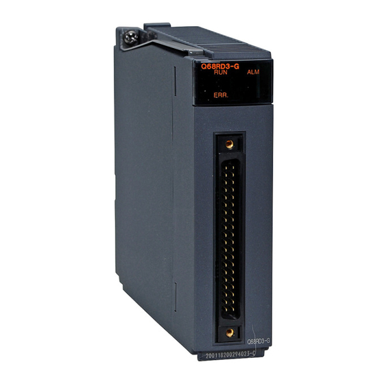
Page 14: Part Names
4. PART NAMES The following explains the part names of the Q68RD3-G. Module fixing screw Module fixing bracket (Connector (Connector terminal terminal number) number) Table 4.1 Part names Number Name Description Displays the operating status of the Q68RD3-G. Normal operation... - Page 15 Table 4.2 Signal name Terminal Terminal Signal name Signal name number number CH1 A1 CH1 B1 CH1 b1 CH2 b2 CH2 A2 CH2 B2 CH3 A3 CH3 B3 CH3 b3 CH4 b4 CH4 A4 CH4 B4 CH5 A5 CH5 B5 CH5 b5 CH6 b6 CH6 A6...
-
Page 16: Wiring
Q68RD3-G. (1) Use separate cables for the AC control circuit and the external input signals of the Q68RD3-G to avoid the influence of the AC side surges and inductions. (2) Always place the RTD at least 100mm away from the main circuit cables and AC control circuit lines. -
Page 17: External Wiring
5.2 External Wiring (1) Wiring procedure 1) For wiring, set a relay terminal block to outside. 2) Connect the RTD to the relay terminal block. 3) Use A6CON4 to wire between the relay terminal block and Q68RD3-G. Q68RD3-G Relay Connector terminal block... -
Page 18: Intelligent Function Module Switch Settings
5.3 Intelligent Function Module Switch Settings (1) Setting item Intelligent function module switch has switches 1 to 5. The setting is executed with 16-bit data. When not setting the intelligent function module switch, the default of switches 1 to 5 is 0. Table 5.1 Intelligent Function Module Switch Settings Setting Item Measuring range setting... -
Page 19: External Dimensions
6. EXTERNAL DIMENSIONS 130 (5.12) (1.85) 27.4 177 (6.97) (1.08) Unit : mm(inch) - Page 20 Warranty Mitsubishi will not be held liable for damage caused by factors found not to be the cause of Mitsubishi; machine damage or lost profits caused by faults in the Mitsubishi products; damage, secondary damage, accident compensation caused by special factors unpredictable by Mitsubishi;...
Need help?
Do you have a question about the Q68RD3-G and is the answer not in the manual?
Questions and answers