Table of Contents
Advertisement
Advertisement
Table of Contents

Related Manuals for Badger Meter Data Industrial 3000 Series


Summary of Contents for Badger Meter Data Industrial 3000 Series
- Page 1 Industrial Flow Monitor Series 3000 User Manual DSY-UM-01667-EN-05 (April 2017)
-
Page 2: Table Of Contents
Industrial Flow Monitor, Series 3000 CONTENTS Introduction . . . . . . . . . . . . . . . . . . . . . . . . . . . . . . . . . . . . . . . . . . . . . . . . . . . . . . . . . . . . . . . . . . . . . . . . . . 3 Safety Information . -
Page 3: Introduction
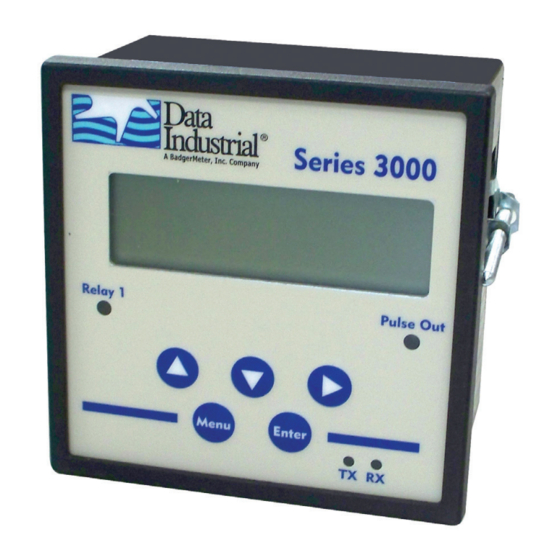
INTRODUCTION The Badger Meter® Data Industrial® Series 3000 flow monitor is an economical, full featured, digital flow monitor . The two-line × 16-character alphanumeric display can be configured by the user to display flow rate and flow total . The panel meter has a NEMA 4X rated front panel and conforms to DIN Standard dimensions, 96 mm ×... -
Page 4: Installation
Installation INSTALLATION Mechanical The Series 3000 flow monitor can be either panel mounted or wall mounted . Location In any mounting arrangement the primary concern is easy viewing and convenient operation of the keypad . The unit generates very little heat, so no consideration need be given to cooling or ventilation . However, prolonged direct sunlight can damage the front panel so some level of shading is recommended, especially if installed in a tropical climate . -
Page 5: Wall Mount Installation
Installation Wall Mount Installation The Series 3000 wall mount flow monitor is designed to mount onto a wall with four bolts or screws . The mounting hole pattern and box dimensions for the Series 3000 NEMA4 wall mount are shown in Figure 4.33 in. -
Page 6: Electrical Installation
LCD/keypad interface . There are no internal or external jumpers, switches or potentiometers to move or adjust . The following pulse input types are accommodated: • Pulse DI: Used for all Badger Meter Data Industrial Flow Sensors . Provides an internal pullup resistor and uses and Offset values for calibration . •... -
Page 7: Analog Input
Installation 1 ANALOG IN+ 2 ANALOG IN- 3 SHIELD 4 SENSOR IN 5 GND 6 SHIELD 7 SENSOR PWR Figure 5: Data industrial flow sensor wiring examples (two- and three-wire pulse types) Analog Input As an alternative to the pulse inputs, the Series 3000 flow monitor can accept an Analog input . The input is non-isolated, but can accept 0…1V DC, 0…5V DC, 0…10V DC, 0…20 mA and 4…20 mA with both factory-defined and custom units of measure . -
Page 8: Solid-State Switch And Form C Output Wiring
Installation Solid-State Switch and Form C Output Wiring The Series 3000 flow monitor has one Normally Open (N .O .) solid-state switch, and one solid-state form “C” relay . See "Specifications" on page 24 for maximum voltage and current ratings for each type output . These outputs are completely independent, electrically isolated, and can be programmed as either Pulse or Set Point outputs . - Page 9 Installation 1 RELAY 1 NO 2 RELAY 1 NC 3 RELAY 1 COM 4 PULSE 1 OUT 5 PULSE 2 OUT Figure 9: Relay and switch wiring examples (continued) High Flow Shutdown and Normally Open Master Valve with Indication 1 RELAY 1 NO 2 RELAY 1 NC 3 RELAY 1 COM 4 PULSE 1 OUT...
-
Page 10: Output Option Card
Output Option Card OUTPUT OPTION CARD If the Series 3000 flow monitor was ordered with the Output Option card, it will have these additional outputs: • Analog Output (0…20 mA; or 4…20 mA), which can be converted externally to 0…5V DC, 1…5V DC with a 250 Ohm resistor, or 0…10V DC or 2…10V DC with a 500 Ohm resistor . -
Page 11: Display And Keypad
2-Move cursor to the right When the Series 3000 flow monitor is first powered up, it runs through internal self checks while displaying “Badger Meter DIC Initializing." At the end of this cycle its normal mode display will appear . -
Page 12: Programming
Programming PROGRAMMING With the normal mode display showing, press Menu to enter the programming mode . In this mode, the three arrow keys () are used on the selection screens to select the option displayed above the key, and on the option list screens to scroll up or down a list of choices, like a pull-down menu . -
Page 13: Programming Flowchart-Software Version 1 .2 .29
Programming Programming Flowchart—Software Version 1.2.29 RESET SETUP DIAG DIAG RESET DIAG ERROR Enter password FLOW1 MODL# SER# REV# 0000 Model #: Serial #: Firmware rev: Reset ow 1? 300010 004620 v1.2.29 OK CANCEL Error codes 000 000 000 000 Reset ow 1? Reset SETUP SETUP... -
Page 14: Flow Inputs Flowchart
Programming Flow Inputs Flowchart Flow 1 setup RATE TOTAL SENSR Continued Flow X total Flow X rate Flow X total UNITS #.DIG CUST UNITS #.DIG CUST RESET at A on next page. Reset BTU total Custom units PASSWD RESET LABEL CONV Enable password? Reset total NOW? 1 unit =... -
Page 15: Flow Inputs Flowchart (Continued)
Programming Flow Inputs Flowchart (continued) Continued from previous page. Sensor 1 type Flow 1 sensor TYPE xxxxxxxx Flow 1 sensor TYPE AVG DICAL Pulse DI DI Sensor Cal. KNUM OFFSET Flow 1 timeconst DI sensor K num Pulse K-Factor Flow 1 sensor +0.00000001 sec 1.00000000 Pullup K-Factor... -
Page 16: Relays & Pulse Outputs Flowchart (Manual, Set-Point Rate And Pulse/Volume)
Programming Relays & Pulse Outputs Flowchart (Manual, Set-Point Rate and Pulse/Volume) SETUP RLY1 Pulse Relay 1 (or Pulse) FUNC xxxxx xxxxx Relay 1 (or Pulse) FUNC MANUAL Manual Control Relay 1 (or Pulse) Relay 1 (or Pulse) Relay 1 (or Pulse) ON [OFF] FUNC INPUT UNITS Rate... -
Page 17: Analog Output Flowchart
Programming Analog Output Flowchart SETUP AOUT1 COMM Analog output 1 FUNC RANGE SCR Analog function Analog output 1 Analog output 1 Analog output 1 Flow Rate FUNC RANGE SCR UNITS LOW HIGH Analog 1 units Analog output Adjust 20 mA Drive source 0 mA = ? 20 mA = ? -
Page 18: Rs485 Communication Port Flowchart
Programming RS485 Communication Port Flowchart Comm NET BAUD ADDR Network Comm Disable Comm MODBUS BAUD ADDR Network Baud Rate MODBUS Address MODBUS 1200 2400 9600 19200 38400 76800 Comm BACnet/MSTP BAUD ADDR MA X DEVID Network Baud Rate MSTP Address MSTP Max master Device Instance BACnet/MSTP... -
Page 19: Communication
Programming Communication RS485 COM Port Configuration The RS485 is very simple to configure . 1 . Select the communications type: Modbus or BACnet . 2 . Choose the BAUD Rate: Auto, 300, 1200, 2400, 9600, 19200, 38400, or 76800 to match the rest of the devices on the network . -
Page 20: Usb Communication
Programming USB Communication If the Series 3000 flow monitor is ordered with an analog output option card, a five-pin USB connector is also included . As much as possible the commands mimic the use of the front panel controls . To use this feature the following are required . - Page 21 6 . When connected, a ">" symbol will appear in the upper left corner of the main HyperTerminal display screen . Press Enter . Both the Rx and Tx LEDs on the front of the Series 3000 flow monitor flash once, and the “Badger Meter DIC … Software Version…”...
-
Page 22: Usb Command List
Programming USB Command List In the list below, brackets indicate an argument, specifying its type and value range . For instance, [0-18] stands for any number between 0 and 18 (inclusive) . Example: “display line1 = 1” sets Line 1 of the display to display #1, which happens to be the totalizer for flow channel 1 . Diagnostics id –... - Page 23 Programming 8: ft3/min 9: ft3/hr 10: m3/s 11: m3/min 12: m3/hr 13: acreft/s 14: acreft/min 15: acreft/hr 16: bbl/s 17: bbl/min 18: bbl/hr 19: Custom flow [1-2] rate ndigits = [2-10] – number of decimal places to show for flow rate flow [1-2] rate custom label = [string] –...
-
Page 24: Specifications
The Americas | Badger Meter | 4545 West Brown Deer Rd | PO Box 245036 | Milwaukee, WI 53224-9536 | 800-876-3837 | 414-355-0400 México | Badger Meter de las Americas, S.A. de C.V. | Pedro Luis Ogazón N°32 | Esq. Angelina N°24 | Colonia Guadalupe Inn | CP 01050 | México, DF | México | +52-55-5662-0882...
Need help?
Do you have a question about the Data Industrial 3000 Series and is the answer not in the manual?
Questions and answers