
Related Manuals for Badger Meter Magnetoflow Mag Meter


Summary of Contents for Badger Meter Magnetoflow Mag Meter
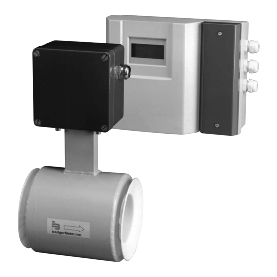
- Page 1 Installation & ® Magnetoflow Wafer Meter Mag Meter with Model Primo ® Operation Manual IOM-103-02 BadgerMeter,Inc. 53400-103 3-09 ®...
-
Page 2: Table Of Contents
SCOPE OF THIS MANUAL UNPACKING AND INSPECTION This manual contains information concerning the installation, opera- Magnetoflow mag flowmeters are shipped in special shipping con- ® tion and maintenance of Badger’s Magnetoflow electromagnetic flow tainers. Upon receipt of the meter, perform the following unpacking ®... - Page 3 Please contact reverse directions (note FORWARD FLOW direction printed on the Badger Meter's Technical Support at 1-800-616-3837 with your detector label). The most recommended installation position is application detail and they can assist in determining if the Mag meter vertical piping, with the liquid flowing upward (see figure below).
- Page 4 PARTIALLY FILLED PIPE SITUATIONS ® Magnetoflow mag meters are designed to operate in closed, full pipes. It is relatively common to encounter situations where the process pipe will remain momentarily partially filled due to certain hydraulic conditions. Examples of this include discharge to the atmosphere (lack of back pressure), insufficient line pressure, gravity flow applications, etc.
-
Page 5: Specifications - Detector
25mm 9.68" 4.58" 246mm 1" 116.5mm 25mm 127mm 83.3mm 3.28" 5" 1" 195mm 7.67" 127mm 5" 89mm 3.52" SIZE ® Meter with junction box for remote Primo converter Meter with Primo ® converter Est. Weight Flow Range with Primo inches mm inch mm inch mm inch inch 1”... -
Page 6: Grounding
® PRIMO AMPLIFIER (3.1 ELECTRONICS) 25mm 9.68" 4.96" 246mm 1" 126mm 11.7" 7.75" 298mm 197mm Mounting Bracket for Remote Configuration SPECIFICATIONS ≤ Galvanic Isolation: 500V Power Supply: 85-265 VAC, 45-65 Hz Zero-point Stability: Automatic correction Power Consumption: 20W LCD Display: 4 lines x 16 character back-lit alphanumeric Accuracy: ±... -
Page 7: Wiring
Remote style Primo Amplifier models can be ordered with longer WIRING cable than our standard stock lengths of the standard cable; 15, 30, 50 and 100 feet. The following chart shows the cable style options At installation, be sure to comply with the following require- and the maximum flow medium temperature that can exist in the ments: application environment at a given length of that cable. - Page 8 This connection is intended for use with indicators that do not require an external power supply such as the ER series indicators from Badger Meter. For the ER-6, ER-8 or ER-9, connect terminal 15 of the Amplifier to terminal 2 of the ER series and terminal 16 to ground or terminal 1 of the ER indicator.
-
Page 9: Programming
the programming parameters, the program returns automatically to PROGRAMMING (3.1 Electronics) the main screen. Even during the parameter setting mode, the meter will be measuring and totalizing any flow that occurs. The Primo ® amplifier comes preprogrammed from the factory and in most instances will not require any additional manipulation. -
Page 10: Full Scale Setting (Maximum Flow)
to "change" and press key. The first unit of measurement screen applications requirements, making sure that it falls within the sug- will appear: gested flow range of the meter. Using the keys,select the desired unit of measure for flow rate When done, press enter and then the key and the next parameter indication. -
Page 11: Empty Pipe Detection
EMPTY PIPE DETECTION The empty pipe detection parameter when programmed to be ON will provide an error relay indication if the meter is partially filled with liquid. This will also show an empty pipe error message on the display. When calibration is complete, hit ENTER. The switching threshold for the empty pipe detection is when the measuring signal “full pipe”... -
Page 12: Filter Dampening
Any error is indicated via the error relay as well as displayed on Relay Wiring Terminals line 4 of the LCD display. The relay is normally closed during normal operation and is opened when an error occurs. Error Relay Using the key select which flow direction mode you want and press ENTER. -
Page 13: Analog Outputs
Line up the > with change and hit key. Press keys until you find the type of analog output that you desire among the following screens: Now line up the > next to the totalizer you wish to reset. Hit key and that totalizer will now indicate "DONE."... -
Page 14: Pulse Outputs
Use the keys to change the value to the desired pulse rate. If calibration is in fact desired, hit ENTER again to get to the following This value may be set from .001 to 10,000 pulses/unit of measure. screen: Maximum frequency of 10kHz can not be exceeded. Based on maximum flow rate setting, the program will not permit a value that exceeds this frequency. -
Page 15: Frequency Output
The following diagram is for other wiring connections for pulse Use the keys to select the minimum flow percentage and outputs. press ENTER; the following screen will appear: FREQUENCY OUTPUT This is the Frequency Output parameter. The setting can range from Use the arrows to change the maximum flow percentage 500 Hz up to 5000 Hz for the Full Scale Value. -
Page 16: Accuracy Test
With this parameter, you can fine tune your calibration to meet your When complete, press Enter. applications needs. If you find that the meter is off by a certain percentage, you can modify the detector factor to achieve the desired accuracy. key to go to the next parameter. -
Page 17: Troubleshooting
TROUBLESHOOTING ® The Magnetoflow mag meter should give you many years of maintenance free operation. However, should it malfunction, there are certain things ® that we recommend you check before contacting our technical support department or your local Badger Representative. Note: If the fluid measured has a high concentration of conductive solids, deposits may accumulate on the internal liner walls and electrodes. -
Page 18: Error Message Explanation
ERROR MESSAGE EXPLANATION Some general conditions to keep in mind: When certain connections are sensed by the electronics, the following error messages can be indicated on the display (line 4) as well as on relay 3. The relay is closed during normal operation and is opened by an error appearing. The following error messages can appear: ERROR MESSAGE POSSIBLE CAUSE... -
Page 19: Board Assembly Replacement
COMPLETE BOARD ASSEMBLY REPLACEMENT ® Make sure power to Primo amplifier is off before proceeding. 1. Pull the electrode, coil and display wiring plugs. Loosen the screws S1 to S5 and remove the existing board assembly. 2. Put in new board assembly and reassemble screws to S1 and S5. - Page 20 Due to continuous research, product improvements and enhancements, Badger Meter reserves the right to change product or system specifications without notice, except to the extent an outstanding bid obligation exists. Please see our website at www.badgermeter.com BadgerMeter,Inc. for specific contacts.
Need help?
Do you have a question about the Magnetoflow Mag Meter and is the answer not in the manual?
Questions and answers