Badger Meter M5000 User Manual
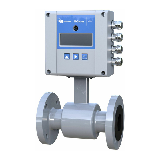
M-series
electromagnetic flow meter
Hide thumbs
Also See for M5000:
- User manual (56 pages) ,
- Installation manual (4 pages) ,
- User manual (24 pages)

Related Manuals for Badger Meter M5000


Summary of Contents for Badger Meter M5000
- Page 1 M-Series® M5000 Electromagnetic Flow Meter User Manual MAG-UM-00219-EN-02 (September 2013) | sales@mvandc.com | Phone: 877.566.3837 | Fax: 925.407.2903 www.mvandc.com...
- Page 2 M-Series® M5000 Electromagnetic Flow Meter Page ii September 2013 | sales@mvandc.com | Phone: 877.566.3837 | Fax: 925.407.2903 www.mvandc.com...
-
Page 3: Table Of Contents
Non-Conductive Pipe Grounding AMPLIFIER MOUNTING CONFIGURATION OPTIONS Meter Mount Configuration Remote Mount Configuration Submersible Option WIRING Wiring Safety Opening the M5000 Cover BATTERY Battery Life Battery Replacement Remote Mount Installation September 2013 Page iii | sales@mvandc.com | Phone: 877.566.3837 | Fax: 925.407.2903... - Page 4 Digital Output Selections PROGRAMMING THE M5000 Function Buttons Display Icons Battery Levels M5000 MAIN MENU PROGRAMMING OPTIONS USING THE M5000 MAIN MENU PROGRAMMING OPTIONS Display Menu Screen Hierarchy Structure SECURITY Setting a PIN Logging In Logging Out Meter Setup Menu...
-
Page 5: Safety Precautions And Instructions
SYSTEM DESCRIPTION The Badger Meter M-Series® model M5000 electromagnetic flow meter is intended for fluid metering in most industries including water, wastewater, food and beverage, pharmaceutical and chemical The basic components of an electromagnetic flow meter are: •... -
Page 6: Unpacking And Inspection
If the unit was damaged in transit, it is your responsibility to request an inspection report from the carrier within 48 hours You must then file a claim with the carrier and contact Badger Meter for appropriate repairs or replacement •... - Page 7 User Manual • Use the sling-rigged method to lift large detectors into a vertical position while they are still crated Use this method to position while they are still crated Use this method to position large detectors vertically into pipelines Figure 3: Sling-Rigged Lifting Methods •...
-
Page 8: Meter Location, Orientation And Applications
M-Series® M5000 Electromagnetic Flow Meter METER LOCATION, ORIENTATION AND APPLICATIONS The M5000 provides two amplifier mounting options: an integral or meter mount option and a junction box/remote option Meter mount amplifier Junction box with remote amplifier Figure 5: Amplifier Mounting Options... -
Page 9: Meter Orientation
Carefully observe the “Forward Flow” label on the meter body and install the meter accordingly When installed vertically, rotate amplifier so that cable glands are facing down Horizontal Placement M5000 meters are equipped with an Empty Pipe Electrode Plane Detection feature If an electrode mounted in the pipe... -
Page 10: Pipe Reducer Requirements
M-Series® M5000 Electromagnetic Flow Meter Pipe Reducer Requirements With pipe reducers, a smaller meter can be mounted in larger pipelines This arrangement may increase low-flow accuracy There are no special requirements for standard, concentric, pipe reducers Custom fabricated pipe reducers must have an approximate slope angle of 15 degrees to minimize flow disturbances and... -
Page 11: Partially-Filled Pipe Situations
User Manual Partially-Filled Pipe Situations In some locations, the process pipe may be momentarily only partially filled Examples include: lack of back pressure, insufficient line pressure and gravity flow applications To eliminate these situations: • Do not install the meter at the highest point of the pipeline •... -
Page 12: Meter Gaskets And Grounding
M-Series® M5000 Electromagnetic Flow Meter METER GASKETS AND GROUNDING Gasket and grounding requirements must be considered when determining the meter location, orientation and application Meter/Pipeline Connection Gaskets You must install gaskets (not provided) between the detector's isolating liner and the pipeline flange to ensure a proper and secure... -
Page 13: Amplifier Mounting Configuration Options
Use twisted pair shielded wire for all output wiring • Observe all applicable, local electrical codes Opening the M5000 Cover The M5000 amplifier's design lets you open the cover without completely removing it Follow these steps: 1 Completely remove the top two screws from the... -
Page 14: Battery
M-Series® M5000 Electromagnetic Flow Meter BATTERY Use a two D-cell battery pack (1/2" to 6") or a double two D-cell battery pack (8" to 24") Battery Life Standard Pack Sampling Expected Life 0 25 3 months 4 years 8 years... -
Page 15: Remote Mount Installation
1 Carefully remove the wires connected to the terminal blocks that run to the M5000 amplifier or to the junction box See the chart below for a reference of wire color to terminal connection... -
Page 16: Configuring Input/Output (I/O)
• Communication When the sensor and the amplifier have been wired, wire any outputs to the M5000 amplifier Follow all of the safety precautions and local code to prevent electrical shock and damage to the electronic components Circuit Board Diagram... -
Page 17: Digital Output Wiring Diagrams
User Manual Digital Output Wiring Diagrams Positive Pulse Logic Negative Pulse Logic Figure 22: Digital Output Wiring Diagram Digital Output Selections Output 1 Output 2 Output 3 Output 4 Flow direction Forward Pulse Output Reverse Pulse Output (Forward vs Reverse) Flow Setpoint Flow Setpoint (0…100% of full scale, resolution 1%) -
Page 18: Programming The M5000
M-Series® M5000 Electromagnetic Flow Meter PROGRAMMING THE M5000 The M5000 amplifier is pre-programmed from the factory No additional programming is necessary, however, for special features, the meter can be programmed for specific requirements Function Buttons All M5000 programming is accomplished using the three function buttons located on the... -
Page 19: M5000 Main Menu Programming Options
User Manual M5000 MAIN MENU PROGRAMMING OPTIONS The following M5000 programming options are available from the Main Menu: • Meter Setup • Measure • In/Out • Communication • Miscellaneous • Information • • Faults The applicable security level for each menu option is indicated as follows:... -
Page 20: Using The M5000 Main Menu Programming Options
M-Series® M5000 Electromagnetic Flow Meter USING THE M5000 MAIN MENU PROGRAMMING OPTIONS Display Menu Screen Hierarchy Structure Main_Menu → Meter Setup → Calibration Scale Factor Frequency Period Empty Pipe Measure → Flow Unit Totalizer Unit Full Scale Flow Low Flow Cutoff... -
Page 21: Security
For a lost PIN, Contact Badger Meter Technical Support at 800-456-5023 for a replacement PIN Not all levels of access need to be set If no PINs are set up, any M5000 user will have access to all functions NOTE:... -
Page 22: Meter Setup Menu
M-Series® M5000 Electromagnetic Flow Meter Meter Setup Menu Meter Setup Calibration Diameter This parameter is set at the factory In the event the amplifier is replaced, verify that the pipe diameter matches the installed pipe size Detector Factor This parameter is set at the factory This factor compensates for accuracy... -
Page 23: Measure Menu
User Manual Measure Menu Measure Flow Unit This parameter establishes the unit of measure for the flow rate and full scale flow Changing this parameter readjusts the full scale flow parameter For example, changing from GPM to GPS would change the full scale flow from 60 gal/min to 1 gal/s Display Flow Unit Display... - Page 24 M-Series® M5000 Electromagnetic Flow Meter Measure Low Flow Cutoff Low flow cutoff defines the threshold at which flow measurement will be forced to zero The cutoff value can be set from 0% to 10% of the full scale flow Increasing this threshold will help prevent false readings during “no flow”...
-
Page 25: Inputs/Outputs Menu
User Manual Inputs/Outputs Menu Inputs/Outputs Flow Simulation Flow Simulation provides output simulation based on a percentage of the full scale flow Simulation will not accumulate the totalizers The range of simulation includes –100…100% of the full scale flow The Flow Simulation Parameter lets you set the range of simulation in increments of 50 (OFF, 0, 50, 100, -50, -100) The factory default is OFF Digital Input •... - Page 26 M-Series® M5000 Electromagnetic Flow Meter Inputs/Outputs Digital Outputs Set Min. This parameter establishes, as a percentage of full scale flow, the threshold at (continued) which the output alarm will be activated Flow rates below the threshold will activate the output alarm Set Max.
-
Page 27: Communication Menu
Modbus Address This parameter configures the Modbus address in the range from 1…247 M-Bus Address MeterBus protocol mainly used in the European market Please direct questions to Badger Meter Technical Support Control ON/OFF Protocol V1 standard messages V2 extended messages Dial 4…9... -
Page 28: Miscellaneous Menu
M-Series® M5000 Electromagnetic Flow Meter Miscellaneous Menu Misc Battery Voltage Displays the current battery voltage This parameter is Read Only Battery Ah Displays the current battery capacity For example, 0/38Ah to 38/38Ah This parameter is Read Only NOTE: A new battery should be at or near a 0/38 reading... -
Page 29: Pin Menu
This function generates a random number which is used when a PIN is lost This number will be needed for Badger Meter Tech Support to provide a Master PIN Emergency Enter the Master PIN received from Badger Meter Technical Support to unlock the meter in case the Admin PIN has been lost Faults Menu... -
Page 30: Maintenance
M-Series® M5000 Electromagnetic Flow Meter MAINTENANCE Mandatory, routine or scheduled maintenance should not be required for the M5000 Mag Meter electronics or flow tube after proper installation However, some occurrences may require personnel to perform the following: • Flow tube and electrode cleaning •... -
Page 31: Troubleshooting
User Manual TROUBLESHOOTING The M5000 mag meter is designed for many years of optimal performance However, should it malfunction, there are certain things that we recommend you check before contacting our Technical Support department or your local Badger Meter Representative... -
Page 32: Errors & Warnings
The Americas | Badger Meter | 4545 West Brown Deer Rd | PO Box 245036 | Milwaukee, WI 53224-9536 | 800-876-3837 | 414-355-0400 México | Badger Meter de las Americas, S.A. de C.V. | Pedro Luis Ogazón N°32 | Esq. Angelina N°24 | Colonia Guadalupe Inn | CP 01050 | México, DF | México | +52-55-5662-0882 Europe, Middle East and Africa | Badger Meter Europa GmbH | Nurtinger Str 76 | 72639 Neuffen | Germany | +49-7025-9208-0 Czech Republic | Badger Meter Czech Republic s.r.o.
Need help?
Do you have a question about the M5000 and is the answer not in the manual?
Questions and answers