
Related Manuals for Badger Meter Data Industrial 3050 Series


Summary of Contents for Badger Meter Data Industrial 3050 Series
- Page 1 Data Industrial® Series 3050 Btu Monitor Series 3050 IMPORTANT: This manual contains important information. READ AND KEEP FOR REFERENCE. Installation & Operation Manual 941700-0030 (6-11)
- Page 2 Series 3050 Btu Monitor Page ii 6-11...
-
Page 3: Table Of Contents
Installation & Operation Manual CONTENTS INTRODUCTION ............................Product Unpacking and Inspection ............................5 Product Description ...................................5 INSTALLATION ............................. Mechanical Installation ................................7 Location ......................................7 Electrical Installation .................................8 OUTPUT OPTION CARD ..........................DISPLAY AND KEY PAD ..........................PROGRAMMING ............................Selection Screens ..................................17 Option List Screens ..................................17 Data Screens .....................................17 USB Communication ................................24 FLOW SENSOR INPUTS .......................... - Page 4 Series 3050 Btu Monitor Page iv 6-11...
-
Page 5: Introduction
A claim for equipment damage in transit is the sole responsibility of the purchaser. Product Description The Badger Meter Data Industrial Series 3050 Btu Monitor is an economical, full-featured compact unit designed for sub-metering applications. The two line x 16-character alphanumeric displays any combination of Energy Rate, Energy Total, Flow Rate or Flow Total. - Page 6 Series 3050 Btu Monitor Series 3050 Btu Monitor Programming The user can program the flow sensor from the front panel by entering a "K" and offset or only a "K" factor, depending on the flow sensor used. Programming is menu driven. All data is entered using the LCD/keypad interface. A password gate is included to prevent unauthorized access to programming parameters.
-
Page 7: Installation
Installation & Operation Manual INSTALLATION Mechanical Installation The Series 3050 Btu Monitor can be either panel mounted or wall mounted. Location In any mounting arrangement the primary concern is easy viewing and convenient operation of the keypad. The unit generates very little heat, so no consideration need be given to cooling or ventilation. However, prolonged direct sunlight can damage the front panel so some level of shading is recommended, especially if installed in a tropical climate. -
Page 8: Electrical Installation
Series 3050 terminal marked (ACC/DC-). If a Badger Meter Data Industrial plug-in power supply (Model A1026, A-503) is being used, connect the black-white wire to the terminal marked (ACL/DC+) and the black wire to the terminal marked (ACC/DC-). - Page 9 The following pulse input types are accommodated. • Pulse-DI: Used for all Badger Meter Data Industrial Flow Sensors. Provides an internal pull-up resistor and uses “K” and “Offset” values for calibration. • Pulse–K Factor: Accepts non zero-crossing inputs but provides no internal pull-up, classical “K” ( pulses/gallon) values for calibration.
- Page 10 Series 3050 Btu Monitor Analog Input As an alternative to the pulse inputs, the Series 3050 can accept an Analog input. The input is non-isolated, but can accept 0-1VDC, 0-5VDC, 0-10VDC, 0-20mA and 4-20mA with both factory-defined and custom units of measure. Low impedance 100 Ohm input for current inputs optimizes performance and flexibility or loop power supplies.
- Page 11 Installation & Operation Manual Temperature Input The Series 3050 Btu Monitor can accept inputs from either a pair of thermistors or RTDs. The inputs are labeled T1 and T2. Since the T1 sensor is used to convert the volumetric flow (Example: GPM) to the mass flow ( Example: Lbs/Hr) used in the Btu calculations, the sensor connected to T1 should be in the same supply or return line as the Flow Sensor.
- Page 12 Series 3050 Btu Monitor Solid State Switch and Form “C” Output Wiring The Series 3050 Btu Monitor has one Normally Open (N.O.) solid state switch, and one solid state form “C” relay. Check the Specifications on page 29 for maximum voltage and current ratings for each type output. These outputs are completely independent, electrically isolated, and can be programmed as either Pulse or Set Point outputs.
- Page 13 Figure 8 Installation & Operation Manual Figure 8 Relay and Switch Wiring Examples (continued) Relay and Switch Wiring Examples (continued) ( Chiller Control based on High Energy Usage with with indication ( Chiller Control based on High Energy Usage with with indication 1 RELAY 1 NO 1 RELAY 1 NO 2 RELAY 1 NC...
-
Page 14: Output Option Card
Series 3050 Btu Monitor OUTPUT OPTION CARD If the Series 3050 Btu Monitor was ordered with the Output Option card, it will have several additional outputs. 1. Analog Output ( 0-20mA; or 4-20mA ) which can be converted externally to 0-5VDC, 1-5VDC with a 250 Ohm resistor; or 0-10VDC or 2-10VDC with a500 Ohm resistor. - Page 15 Installation & Operation Manual Modbus points All of the following are available as Input Registers. Figure 12 Addr Function RS485 Communication 1. Flow 1 Rate (GPM) 2. Flow 2 Rate Model 3700 3. Flow 1 Total (gallons) 1 RS485 B Model 345WT 2 RS485 A or other...
-
Page 16: Display And Key Pad
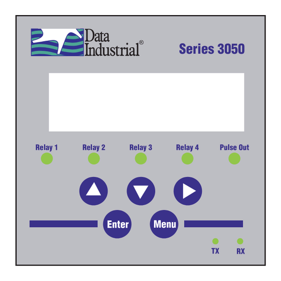
Two of the keys( Menu and Enter) serve a single function while the three remaining keys () serve dual purposes. When the Series 3050 is first powered up, it runs through internal self checks while displaying “Badger Meter DIC Initializing." At the end of this cycle its normal mode display will appear. -
Page 17: Programming
Installation & Operation Manual PROGRAMMING With the normal mode display showing, pressing the Menu key will enter the programming mode. In this mode, the three arrow keys () are used on the selection screens to select the option displayed above the key, and on the option list screens to scroll up or down a list of choices, like a pull-down menu. - Page 18 Series 3050 Btu Monitor Page 18 6-11...
- Page 19 Installation & Operation Manual Page 19 6-11...
- Page 20 Series 3050 Btu Monitor Page 20 6-11...
- Page 21 Installation & Operation Manual Page 21 6-11...
- Page 22 Series 3050 Btu Monitor Page 22 6-11...
- Page 23 Installation & Operation Manual Page 18 Page 23 6-11...
-
Page 24: Usb Communication
Series 3050 Btu Monitor USB Communication If the Data Industrial Series 3050 Btu Monitor is ordered with an Analog Output Option card, a five-pin USB connector is also included. As much as possible the commands mimic the use of the Front Panel controls. To use this feature the following are required. - Page 25 6. When connected, a ">" symbol will appear in the upper left corner of the main HyperTerminal display screen. Press the “Enter Key. ” Both the Rx and Tx LEDs on the front of the Series 3050 should flash once, and the “Badger Meter DIC …...
- Page 26 Series 3050 Btu Monitor USB COMMAND LIST FLOW INPUT CHANNEL CONFIGURATION flow [1-2] sensor type = [0-4] – flow sensor type: In the list below, brackets indicate an argument, specifying 0: PulseDI, its type and value range. For instance [0-18] stands for any 1: PulseKFactor, number between 0 and 18 (inclusive).
- Page 27 Installation & Operation Manual BTU CONFIGURATION RELAY OUTPUT CONFIGURATION Btu rate units = [0-5] – set the Btu rate units: relay [1-5] func = [0-9] – relay function; relay 5 is the pulse 0: kBtu/hr output 1: Btu/min 0: Totalizer 2: kW 1: Alarm 3: TR...
- Page 28 Series 3050 Btu Monitor RS485 COMM PORT CONFIGURATION TROUBLESHOOTING Trouble Codes: comm baudrate = [0-7] 0: Auto 1: 300 1 Relay 1 totalizer rate exceeded 2: 1200 2 Relay 2 rate exceeded 3: 2400 3 Relay 3 rate exceeded 4: 9600 4 Relay 4 rate exceeded 5: 19200 5 Pulse out rate exceeded...
-
Page 29: Flow Sensor Inputs
Installation & Operation Manual FLOW SENSOR INPUTS Type Threshold Signal Limit Frequency Pull-up Impedance Aux. Power Calibration Pulse-Di 2.5 VDC 30VDC 0.4 Hz to 1K to12VDC — 12VDC@30mA K + Offset 10kHz Pulse-K Factor 2.5 VDC 30VDC 0.4 Hz to —... - Page 30 Series 3050 Btu Monitor Intentionally blank page Page 30 6-11...
- Page 31 Installation & Operation Manual Intentionally blank page Page 31 6-11...
- Page 32 Please see our website at www.badgermeter.com for specific contacts. Due to continuous research, product improvements and enhancements, Badger Meter reserves the right to change product or system specifications without notice, except to the extent an outstanding contractual obligation exists. Badger Meter | P.O.
Need help?
Do you have a question about the Data Industrial 3050 Series and is the answer not in the manual?
Questions and answers